Instruments by Science Group
I12 Contact
Science Group Leader
Julia Parker
Email: [email protected]
Tel: +44 (0)1235 778924
I12 JEEP: Joint Engineering, Environment and Processing
Status: Operational
Beamsize: From 50 micrometer x 50 micrometer to 50 mm x 15 mm (EH1) or 100 mm x 30 mm (EH2)
Energy: 53 – 150 keV
Energy: 53 – 150 keV
IMPORTANT INFORMATION FOR USERS BRINGING THEIR OWN SAMPLE ENVIRONMENTS
We receive many requests to “integrate” sample environments with the beamline control system. This places a great demand on Beamline Staff and Diamond support teams and we cannot possibly accommodate all requests.
Requests to integrate a rig so that it can be controlled by the beamline’s EPICS control system and GDA data acquisition system will generally be declined. Where a user group or community of users could benefit from rig integration, then this can be discussed with the I12 Principal Scientist.
Please note that Diamond does not support LabView.
Instead, there are passive ways in which data from users’ rigs can be collected and stored along with beamline diffraction data:
- 0 - 10 V analogue signals at a rate of up to 10 Hz. Signals shall be provided by the user via a BNC coaxial connector with 50-ohm impedance.
- Temperatures using K-type or R-type thermocouples. Please discuss your requirements with your local contact.
- Digital level signals of TTL type. Signals shall be provided by the user via a BNC coaxial connector with 50-ohm impedance. For example, a TTL signal from a user’s rig can be used to trigger detectors in some circumstances. Alternatively, the beamline control system can send TTL signals to a user rig.
Users can control their rigs using their own computer and software on a private network.
- It is not permitted to have user computers connected to the beamline network.
- WiFi will not work for communication with devices inside a closed X-ray hutch.
- The user's computer requires a free Ethernet adapter.
- The user must have administrator rights on their machines in order to set up a local network or remote desktop connection. To avoid delays during beamtime, please check that your connection method works with your equipment before arrival at Diamond.
- Ethernet patch panels are available to connect user equipment in the hutch with a user’s control computer in the beamline control room.
- A user chicane is available if other cables need to be routed to the control room. Please, read the description of Experimental Hutches carefully.
- USB is not recommended due to the restriction on cable length to ~ 3 m. If using a USB is unavoidable, users are responsible for providing their own USB extenders. USB to Ethernet is recommended.
Sample Environments at Beamline I12:
Beamline I12-JEEP has some sample environments available to users. Due to our diverse user community, it is not possible to provide every sample environment that a user might need. Instead, the beamline is capable of accepting a wide variety of user-owned sample equipment. If you plan to bring your own equipment, please contact Beamline Staff to discuss your requirements and confirm technical feasibility before submitting a proposal.
| Equipment | Main parameters | Description |
| INSTRON 100 kN uniaxial servo-hydraulic mechanical test rig | 100 kN load cell. 10 kN load cell can be piggy-backed in place (rarely used). 175 mm actuator stroke. - Fatigue at up to 20 Hz. - Grips for Flat, Round and Compact Tension specimens. - Compression platens. - Hydraulic grips. |
- Contact Beamline Staff to discuss your proposal before submission. - Please request in the beamtime proposal. |
| Custom designed ODISC heating furnace | 100 °C - 900 °C. |
- Contact Beamline Staff to discuss your proposal before submission. - Please request in the beamtime proposal. |
| Cryostream | approx. 80 - 473 K (-153 °C to 200 °C). | - Please request in the beamtime proposal. - Time for equipment setup (~3-4 h). - To avoid a large temperature gradient, sample should have size below 3 mm in horizontal directions. |
| Custom designed HELIOS heating furnace | 200 °C - 1300 °C. The hot spot size approx. 2x2x2 mm3. |
- Contact Beamline Staff to discuss your proposal before submission. - Please request in the beamtime proposal. |
| Custom designed metal heating block | 25 °C - 100 °C. |
- Contact Beamline Staff to discuss your proposal before submission. - Please request in the beamtime proposal. |
|
Linkam TS1500 heating furnace |
Small hot stage for heating samples up to 1300 °C in inert gas purge or in vacuum |
- Contact Beamline Staff to discuss your proposal before submission. - Please request in the beamtime proposal. Specifications: |
| Linkam MFS600 (small mechanical test rig) |
A small system that can apply and measure a tensile/compressive force on a sample while controlling the temperature of the sample. |
- Contact Beamline Staff to discuss your proposal before submission. - Please request in the beamtime proposal. |
Sample Environments belonging to other beamlines that Beamline I12 can borrow, subject to availability:
| Equipment | Main parameters | Description |
| Large electromagnet | Permanent magnetic field in the range 0 – 1 T without polarity switching. |
- Used by special arrangement only. - Contact beamline staff to discuss your proposal before submission. - Please request in the beamtime proposal. |
Sample Environments belonging to other organisations that I12 users can borrow
Sample Environments belonging to other organisations that I12 users can borrow, subject to agreement between users' group and corresponding organisation.
| Equipment | Main parameters | Description |
|
INSTRON 3 kN Electro-Thermo-Mechanical Tester (ETMT) |
- Direct electrical resistance heating of sample. - Heating rate up to 200 °C/s. - Cooling rate up to 100 °C/s. - Optional inert gas environment |
- The ETMT is owned by the University of Manchester at Harwell (UoMaH). The use of this equipment for beamtime or offline work must be agreed with UoMaH ([email protected]) before submitting a proposal. - Proposals are required to include a UoMaH staff member as co-investigator (after proposal acceptance at the latest). |
1. INSTRON 100 kN uniaxial servo-hydraulic mechanical test rig
- General
The rig is a 100 kN uniaxial servo-hydraulic system with an 8800MT controller. Control is possible using Instron’s standard Console and WaveMatrix software. The rig is also integrated with the beamline’s EPICS control system, with a user interface that emulates the main functionality of Instron’s Console software. The majority of users prefer to control the rig using Instron’s software, because they are already familiar with it from rigs at their own institution.
The beamline staff have limited resources for training new or inexperienced users. As similar rigs are widely available in Universities, users are advised to undertake preliminary training at their own institution before performing experiments on I12.
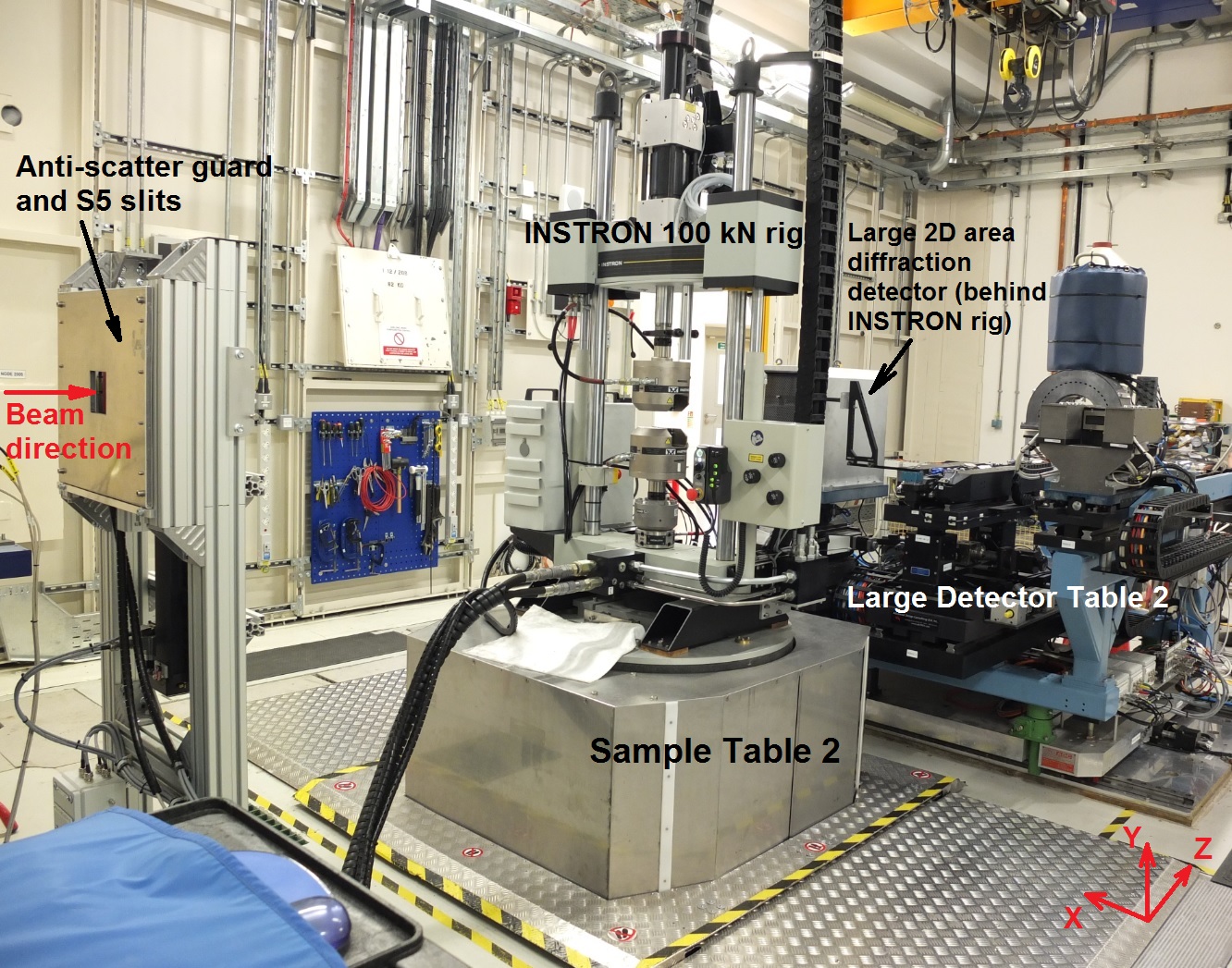
INSTRON 100 kN uniaxial servo-hydraulic mechanical test rig installed on Sample Table in Experimental Hutch 2 for diffraction strain mapping experiment.
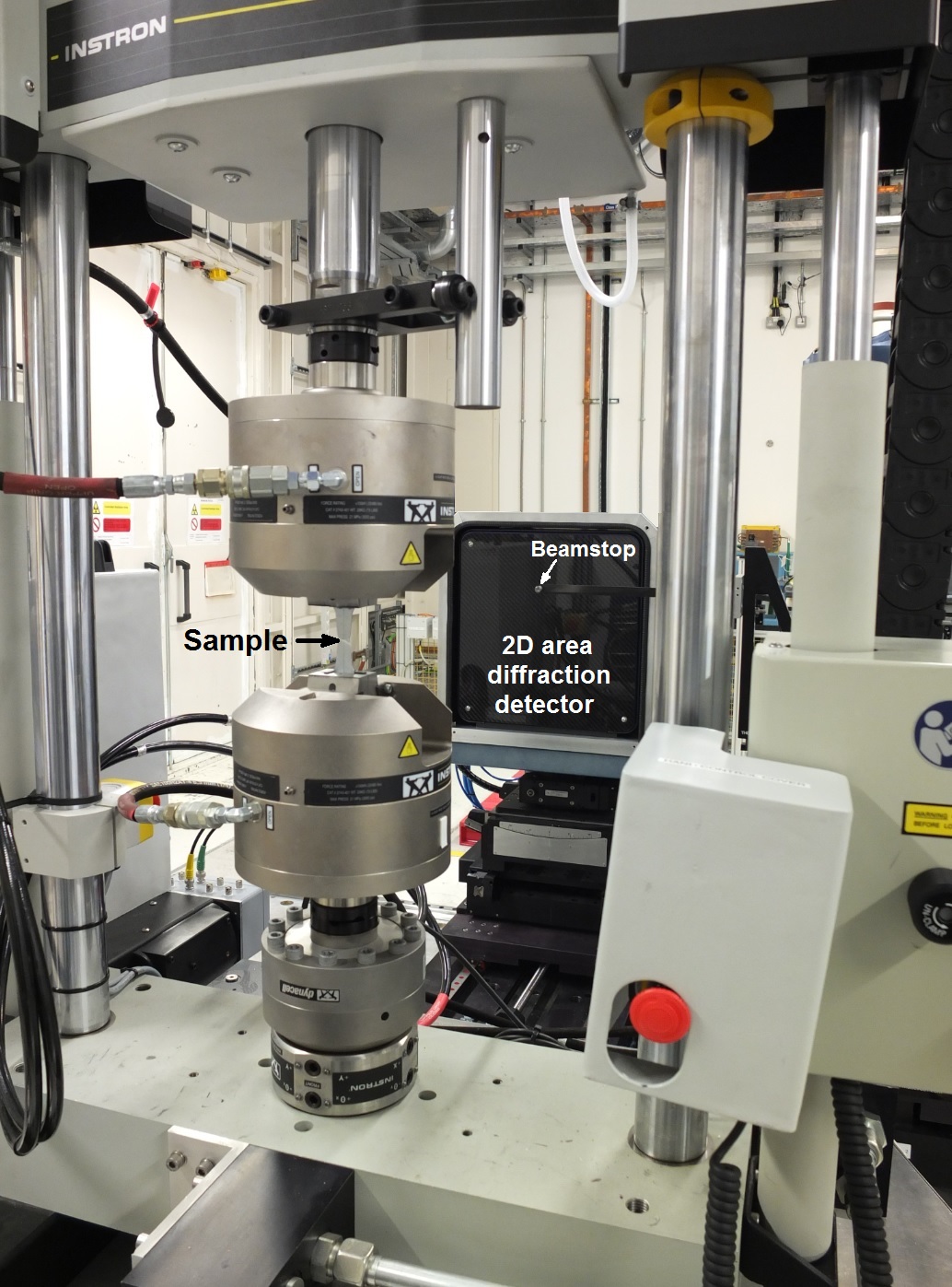
INSTRON 100 kN uniaxial servo-hydraulic mechanical test rig with sample installed in 100 kN load cell for diffraction strain mapping experiment (sample is broken). 2D area diffraction detector is off-centered with respect to the beam.
Transducers:
- 100 kN load cell.
- Optional 10 kN load cell that can be installed on top of the grips. This load cell is rarely used.
- LVDT on the actuator for displacement measurement.
- Clip gauge with 5 mm range.
- Optional strain gauge input.
The rig is mounted on the Large Sample Table in Experimental Hutch 2.
Fatigue testing at up to 20 Hz is possible, depending on the sample type and amplitude required. Note that fatigue tests are paused when taking X-ray imaging or diffraction data.
Good control of tests in Load Control requires tuning of the controller parameters. We recommend bringing at least three spare samples for control loop tuning at the start of the experiment.
- 100 kN Hydraulic Grips
The rig has fatigue-rated hydraulic grips.
There are four sets of jaw faces available to accommodate different specimens. Users shall design their specimens to a well-known international standard for mechanical testing, with appropriate grip ends. We require that the specimen ends are at least 25 mm long, however the official Instron recommendation is 37.5 mm, i.e. 75% of the grip length).
| Instron Part No. | Description | Capacity | Grip length |
| 2704-521 | Flat jaw faces | 0 to 7.8 mm thick | 50 mm |
| 2704-522 | Flat jaw faces | 7.1 to 15.7 mm thick | 50 mm |
| 2704-523 | Vee jaw faces | 6.1 to 11.9 mm diameter | 50 mm |
| 2704-524 | Vee jaw faces | 9.9 to 16 mm diameter | 50 mm |
If you choose to use flat specimens, note that the grips are aligned so that the flat face of the sample is perpendicular to the incident X-ray beam, as shown in the diagram below.
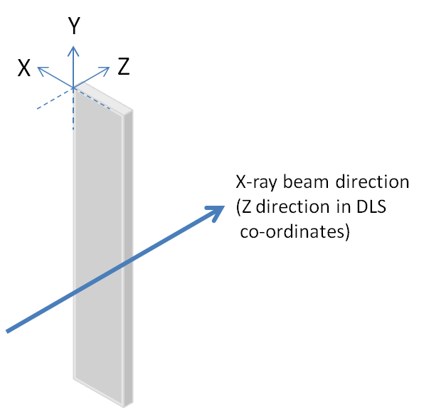
Flat specimen orientation with respect to X-ray beam.
- 10 kN Tensile Only Grips
There are 10 kN Tensile only grips available for use with the 10 kN load cell.
Different jaws available, which are tightened by hand to secure the specimens.
For convenience, the jaws have been pre-assembled with wedge adapters, which fit the 100 kN hydraulic grips, so the grips and 10 kN load cell are piggy-backed onto the hydraulic grips.
- Fracture Mechanics Grips
Instron Catalogue No. 2750-084.
Fracture Mechanics Grips For 12.7 mm (0.50 in) Thick Specimens.
Suitable for fatigue crack growth and JIC testing of "1T" compact tension specimens (not suitable for KIC testing of "1T" specimens).
Capacity: 110kN Static or 55kN Dynamic.
Clevis Pin diameter limits of size according to drawing: 0.470 to 0.480 inches (11.938 to 12.192 mm).
Mechanical interface: M30 x 2 right hand female threads.
Requires: fatigue rated adapters.
- Wedge Blocks
There are two pairs of wedge blocks which can be installed in the grips instead of the jaw faces. The wedge blocks have M30 x 2 mm pitch RIGHT HAND threads for the attachment of other grips and accessories.
There is one pair of low profile adapters, and one pair of high profile adapters.
The high profile adapters are MANDATORY for mounting "piggy back" load cells and other fixtures, in order to avoid the hydraulic grips fouling on accessories if accidentally opened.
Do NOT use the low profile adapters without first checking if the hydraulic grips could foul the accessory installed on the adapter.
- Compression Plattens
Plattens for compression testing are available. Due to the small separation of the plattens in most compression tests, diffraction signals from samples may be obscured in the vertical plane.
- Tomography with the 100 kN Instron.
Limited angle tomography is possible, covering an angular range of ~ 135 degrees instead of the usual 180 degrees. Users can expect to see some artefacts in their tomography scans because of the limited angle. However, experience has shown that acceptable results can be obtained. Iterative reconstruction methods may help to reduce artefacts. Due to the mass of the rig, maximum tomography rotation speed is limited to 2 degrees per second. Optical modules 1, 2 and 3 can be used for tomography with INSTRON, but optical module 4 cannot be used due to the eccentricity of the Large Sample Table. Please, read the description of imaging cameras for tomography.
For limited angle tomography, the sample gauge length must be longer than for diffraction measuremetns. The ROI should be at least 75 mm above the lower grip. To inspect a central part of the sample the sample gauge length must be at least 2×75 mm + vertical ROI size.
The following table summarises tomography- and radiography-specific parameters for four optical modules with PCO.edge visible light sensor and with MIRO 310M visible light sensor which can be used as a reference for planning experiments with INSTRON 100kN rig (important: these two sensors cannot be used simultaneously). Note: these values are for guidance only; INSTRON can be installed only in Experimental Hutch 2. Continuous rotation of INSTRON 100kN rig is not possible.
| High-resolution configuration (with PCO.edge visible light sensor) | High-speed configuration (with MIRO 310M visible light sensor) | |||||
|
Optical |
Field of view, hor × ver [mm] | Pixel size [square shape, µm] |
Usual measurements time per one tomography rotation for monochromatic beam |
Field of view, hor × ver [mm] | Pixel size [square shape, µm] | Usual measurements time per one tomography rotation for monochromatic beam |
| Module 1 | EH2: 46 × 20 | 18.53 | 10-20 mins | EH2: 46 × 20 | 38.10 | Tomography with MIRO camera is not possible due to heavy weight of the INSTRON 100kN rig and attached hoses. Only fast radiography is possible. |
| Module 2 | EH2: 20 × 17 | 7.91 | 10-20 mins | EH2: 20 × 20 | 16.26 | |
| Module 3 | 8.0 × 7.0 | 3.24 | 20-30 mins | 8.5 × 5.3 | 6.67 | |
| Module 4 | 3.3 × 2.8 | 1.30 | n/a * | 3.4 × 2.1 | 2.67 | |
* Tomography in EH2 using optical module 4 is affected by the eccentricity of the Large Sample Table.
Selecting monochromatic or white beam for high speed imaging with MIRO 310M depends on the attenuation of your sample.
It is possible to use a filtered white beam to gain higher speed, however the contrast and the image quality will be decreased.
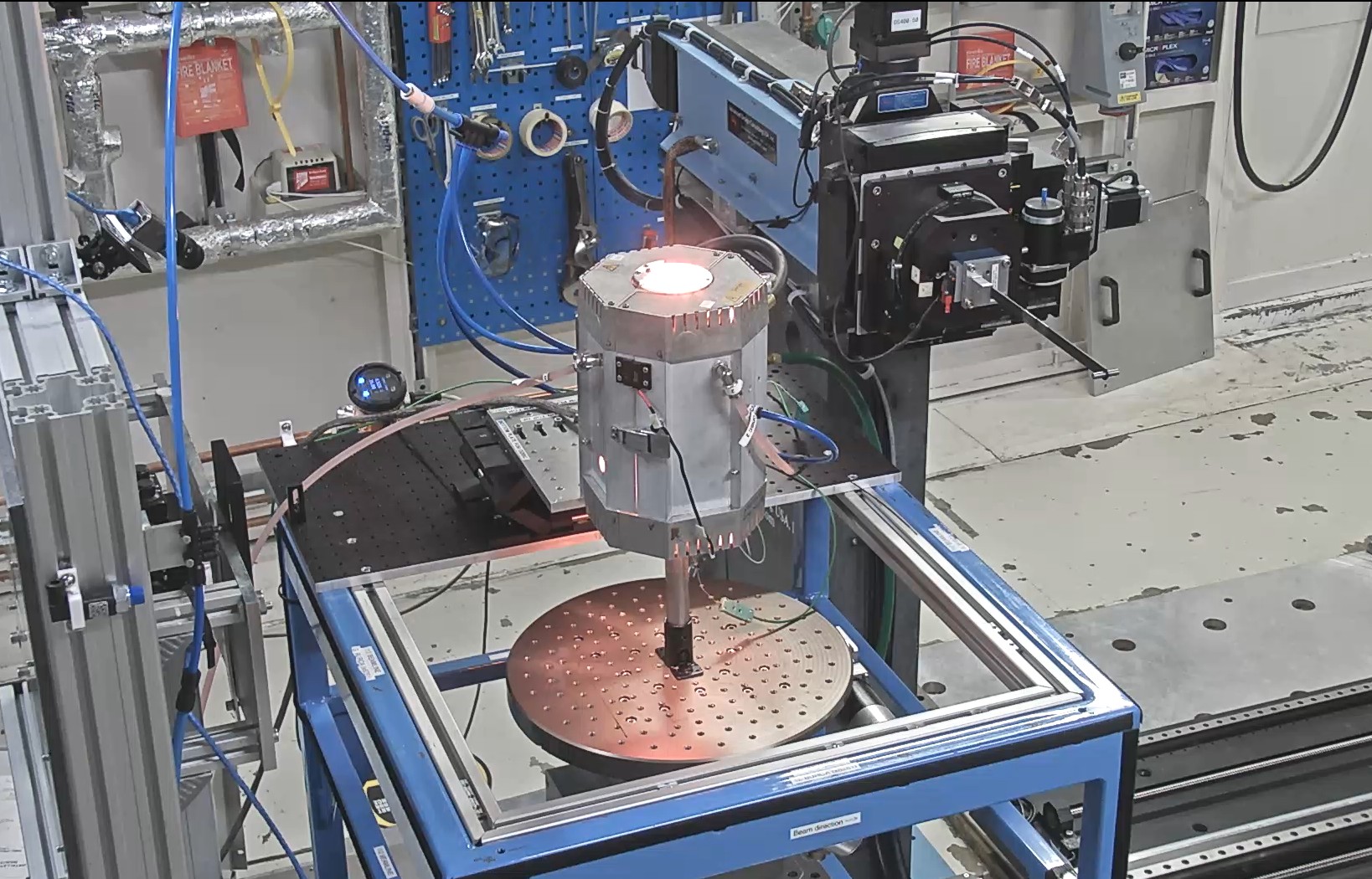
Video of experimental setup with INSTRON on Sample Table 2 for limited angle tomography can be viewed below (rotation of Sample Table 2 with real rotation speed):
2. ODISC heating furnace
Introduction
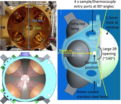
The ODISC (Oxford-Diamond In Situ Cell) furnace was designed on I12 for in situ chemical experiments, but it can also be used for other experiments that require heating large samples.
Please refer to the publication for more technical details: S.J. Moorhouse, N. Vranješ, A. Jupe, M. Drakopoulos, D. O’Hare. Review of Scientific Instruments, 83, 084101 (2012)
Contact Beamline Staff to discuss your proposal before submission.
Capabilities
The ODISC furnace has been designed for temperatures up to 1200 °C. Health & Safety and operational reliability considerations require a maximum temperature of 900°C.
- Reliable operating temperatures 100°C - 900°C
- Compatible with fixed-energy diffraction (XRD)
- Compatible with fixed-angle energy dispersive diffraction (EDXRD)
- Compatible with full 180° tomography (XCT)
- Compatible with combined XCT/ XRD/ EDXRD modalities
- Not compatible with fluorescence imaging (F3CT)
- ODISC is an IR (infrared heated) furnace with an important XZ thermal gradient (Y is mostly uniform)
Supplies
Please note that:
- We do not supply quartz tubes
- We do not supply sample holders
- We only supply BASIC k-type thermocouples where needed
- We have an autoclave (see details below)
- We provide PTFE inserts for metal autoclaves (up to 250°C)
- ODISC drawings can be downloaded here.
Conventional experiments
-
The sample holder sits on the tomography stage
-
Compatible with XCT & XRD
-
We do not supply sample holders
-
We can supply baseplate attachments
-
Thermocouples must touch the sample
Sample holder considerations:
- Should have a low thermal expansion coefficient (to avoid sample movements and XRD misalignment)
- Should not react to oxygen when heated (e.g., copper) or produce any dust when heated
- Should be a thermal insulator, to avoid conducting heat to the sample stage
- Should have its own K-type thermocouple integrated, ideally contained within the column, isolated, and touching the sample from underneath
- Should have a second control thermocouple where possible, touching the sample
- Where a quartz tube is used, the thermocouple should contact the tube from underneath, or if contact with the sample is needed, enter the tube from the top (with a very long insulated cable)
⇒ ODISC drawings can be downloaded here.
Chemical reactions experiments (with mixing/autoclave)
⇒ Only compatible with XRD
Users can design and manufacture their own inserts for available metal autoclaves (drawings available as PDF and STEP files) for their specific research projects. Users can also design their own sample chambers instead of the metal autoclave or quartz tubes available on the beamline; the corresponding drawings of the furnace ODISC (PDF and STEP files with dimensions) can be downloaded here.
The ODISC furnace can be used for two types of experiments aiming at in situ measurements during chemical reactions.
a) In situ measurements of reaction kinetics during solvothermal synthesis experiments, which are performed at temperatures below the boiling temperature of the solvent.
This type of experiment can be performed using quartz tubes with screw caps.
Important: users must bring their own quartz tubes with caps that fit the thermocouple for insertion into the solution. The outer diameter of quartz tubes must be below 15 mm, and their height should be above 80 mm. The beamline does not provide quartz tubes to users. Check that metal thermocouples will not dissolve in your solution!
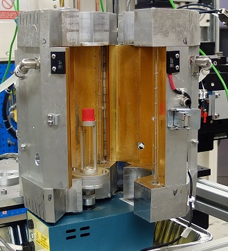
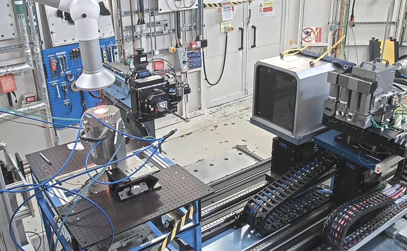
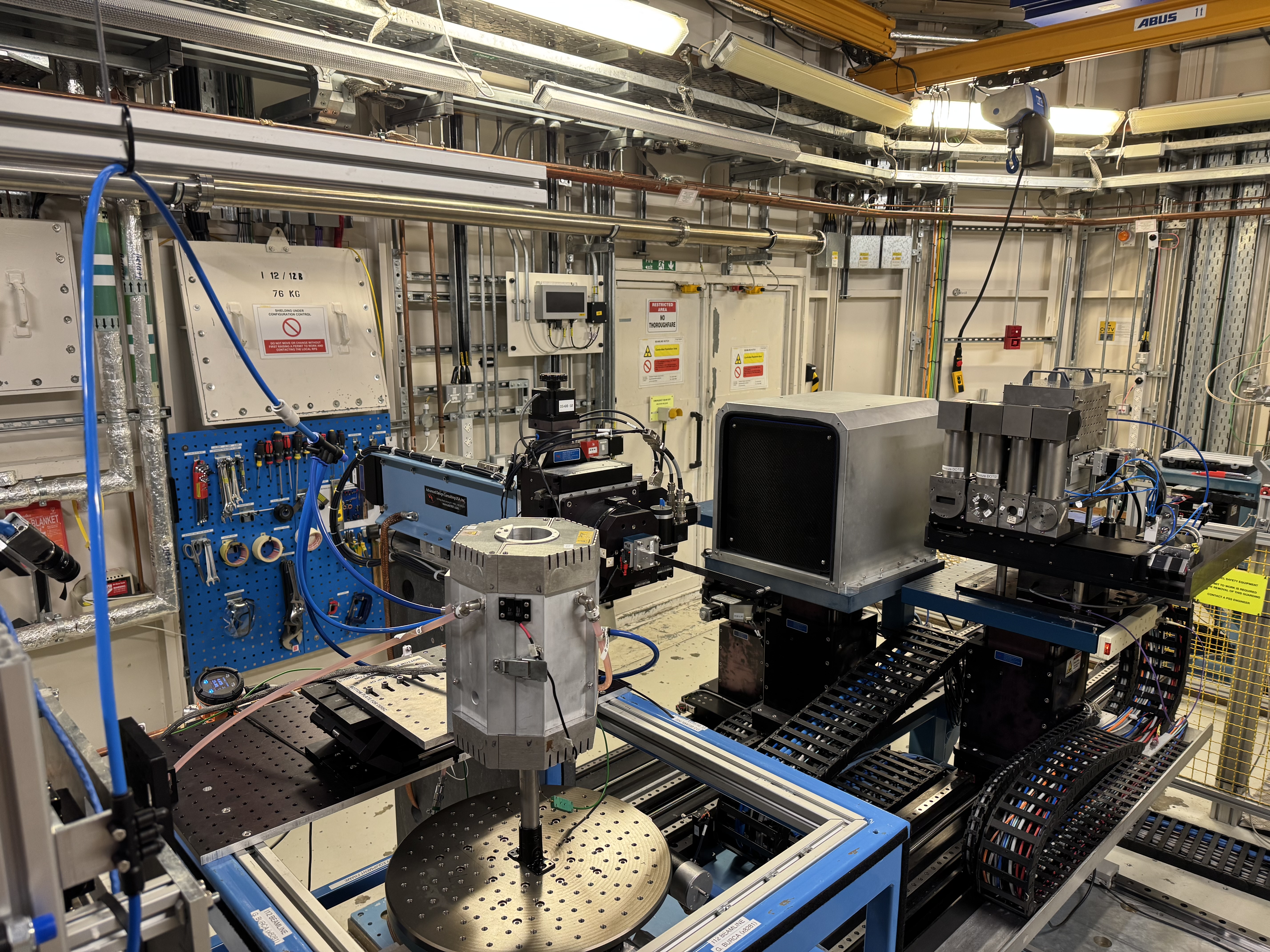
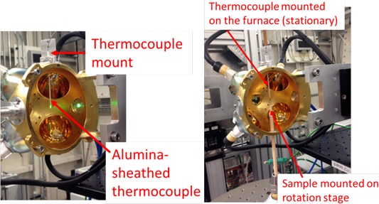
ODISC furnace installed on Sample Table 1 with quartz tube inside and mixer (not compatible with tomography).
b) In situ measurements of reaction kinetics during hydrothermal synthesis or high-temperature solid-state synthesis can be performed in metal autoclaves. The excess pressure during synthesis must not exceed 50 bars – the maximum pressure allowed for metal autoclaves on beamline I12.
If you plan to perform the in situ measurements of reaction kinetics during hydrothermal synthesis on beamline I12, you are allowed to investigate only those reactions for which you confirmed that the maximum excess pressure during reaction is below 50 bar. The beamline provides suitable PTFE inserts for metal autoclaves, allowing experiments to be performed at temperatures below 250 °C (above 250 °C, the PTFE inserts will melt).
If you plan to perform in situ measurements of reaction kinetics during high-temperature solid-state synthesis, you must prepare completely sealed quartz tubes or containers suitable for all starting materials before your beamtime.
Important: Diamond does not have suitable laboratory equipment for sealing quartz tubes under vacuum or inert atmosphere. The beamline does not provide any suitable quartz tubes or containers for use with a metal autoclave. The size of your containers or quartz tubes must fit inside the beamline’s metal autoclave.
The temperature distribution within the ODISC is uneven (thermal gradient from IR radiation); please keep this in mind if you plan to use it with very small samples (1-5 mm). The temperature distribution within the ODISC has no effect on experiments involving the quartz tubes or metal autoclaves specified above.
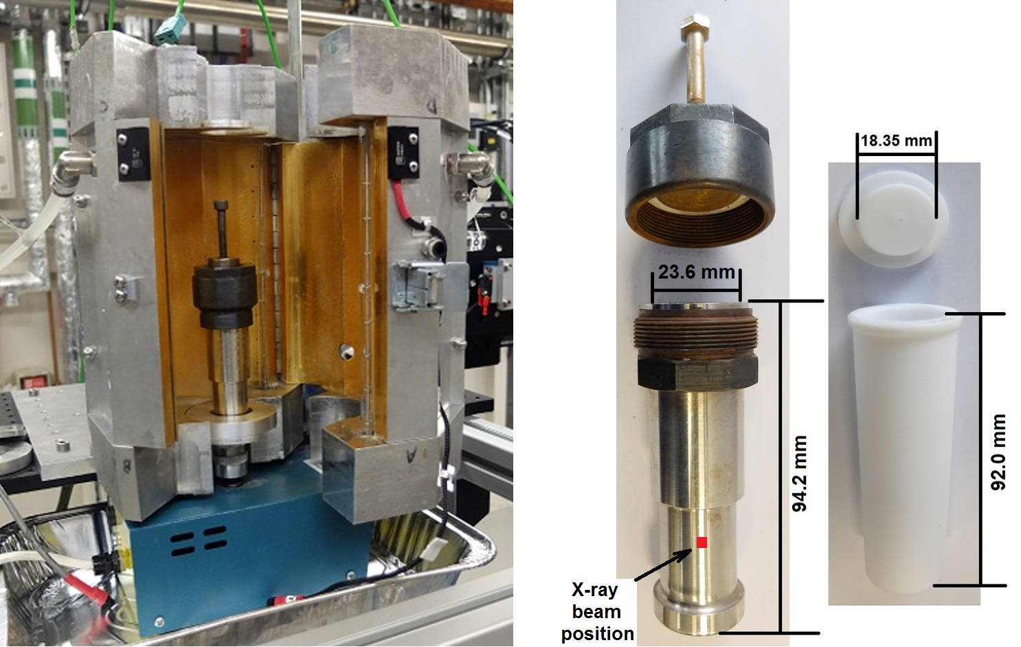
ODISC furnace installed on Sample Table 1 with metal autoclave inside (left) and metal autoclave and PTFE insert with dimensions (right).
3. Cryostream
Standard laboratory Oxford Cryostream 700 can be used for heating/cooling small samples in the temperature range 80 K - 473 K (or -153 °C to 200 °C).
Heating/cooling is performed by nitrogen gas flow. The nose of cryostream has small exit window for nitrogen gas of 5 mm diameter, thus only small objects can be used for efficient heating/cooling with cryostream. To avoid a large temperature gradient, your sample should have size below 3 mm in horizontal directions.
If you plan to use the cryostream with your equipment (i.e. with loading rigs or special cells), you should think about the suitable arrangement of your equipment and cryostream so that the X-ray beam path remains clear (not obstructed by parts of any equipment) for incoming X-ray beam and for diffracted X-ray beam.
4. Custom designed HELIOS heating furnace
Heating furnace HELIOS was designed on I12. It consists of four lamps and dedicated for high temperature (up to 1300 °C) powder X-ray diffraction and imaging studies in air in transmission geometry. The hot spot size is limited – approx. 2×2×2 mm3. Because of rapidly changing resistance of the lamps at low temperatures/power, the temperature stability and ramp control are not reliable below 200 °C.
Four lamps are focused towards a common point at centre of the furnace. Sample can be mounted from the top, bottom or side. The front of the furnace is covered by an aluminium hemisphere lid. Two front lids are available, with hole sizes of 2 mm and 25 mm, respectively.
Two mounts (image on the left) for capillaries (diameter 1.5 mm or 2.0 mm) or for thermocouples are available for X-ray powder diffraction measurements with HELIOS furnace. A goniometer head (image on the left) can be used to mount the sample on the sample stage for tomography or diffraction measurements.
Important: furnace HELIOS can be used either with K-type, or with R-type thermocouples, but not with both types of thermocouples in the same experiment (high-temperature limit for K-type thermocouples is approx. 1100°C; R-type thermocouples must be used for temperatures above 1100°C). Users must clearly specify the type of thermocouples before the experiment. Due to the expense of R-type thermocouples, we request that users bring these thermocouples for their experiment. Purchasing bare R-type wires for assembling your own thermocouples is more cost effective than buyig pre-made ones.
A spot welder is available for making thermocouple junctions and for welding thermocouples to samples.
5. Custom designed metal heating block
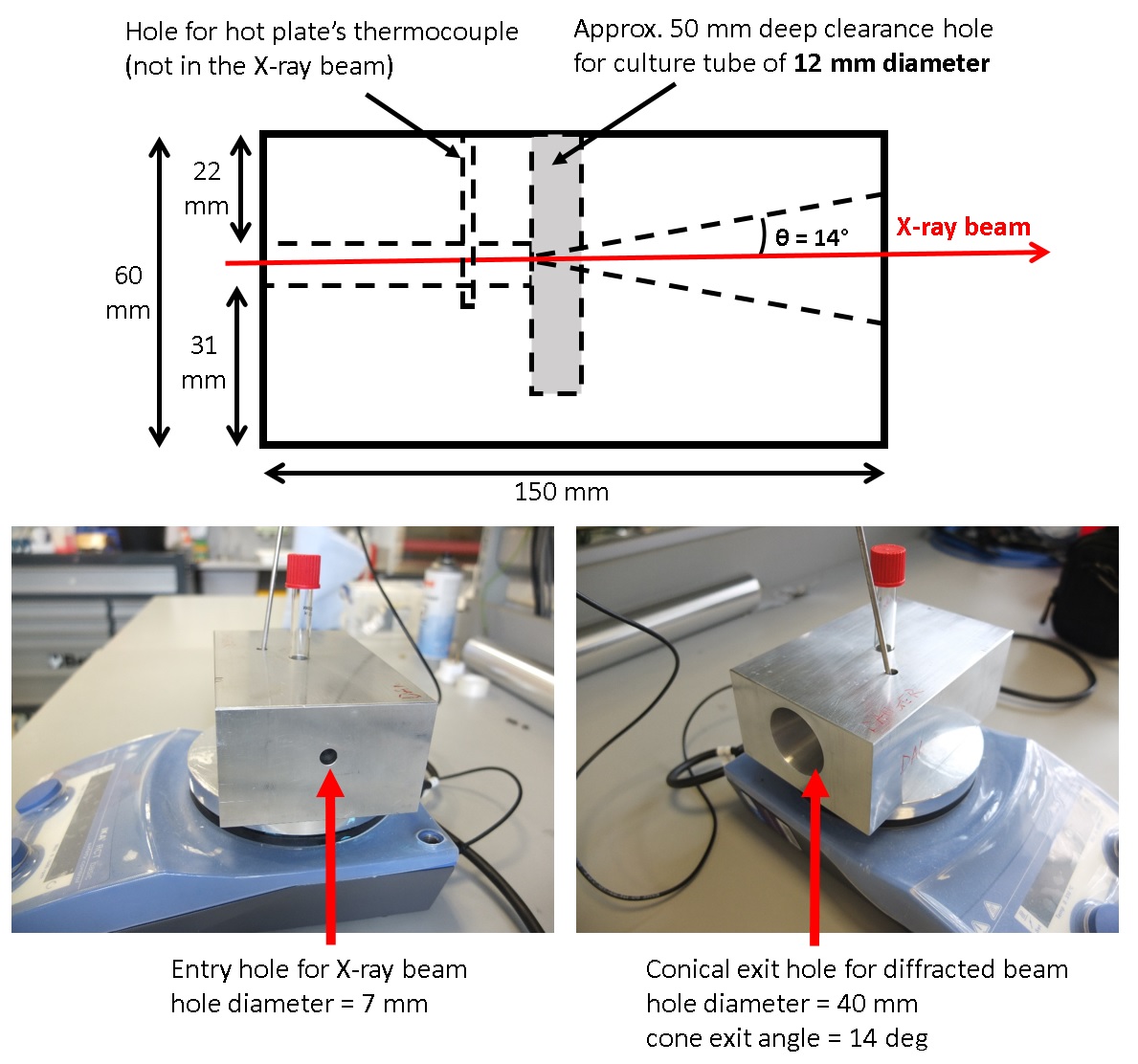
Schematic and photos of custom design metal heating block for in situ chemistry measurements with magnetic hotplate stirrer.
Metal heating block is designed for low temperature in situ chemistry experiments - from room temperature to approx. 100 oC. It can be used with magnetic hotplate stirrer, allowing to mix substance during the measurements providing the homogeneous distribution of material in the reaction tube. This configuration enables in situ measurements of the kinetic of chemical reactions from diffraction measurements for crystalline materials.
Users can design and bring their own metal block according to specifications listed above.
Important: users must bring the sufficient amount of their own reaction quartz tubes. The outer diameter of quartz tubes must be 12 mm (there are two different option available to order – 12 mm and 13 mm; please check also the height of your tubes! It is the responsibility of users to bring suitable quartz tubes). Beamline does not provide quartz tubes for users.
6. Linkam TS1500 hot stage
The Linkam TS1500 hot stage is a small platinum resistance commercial furnace for measurements from room temperature to 1300 °C in Ar gas flow or under vacuum. The hot stage is dedicated only for high temperature X-ray diffraction measurements in transmission mode. Additionally, the inner furnace part can be purging with gas (Ar or N2, not He, not H2) to protect samples against oxidation.
For measurements above 600 C, the Ar gas flow or vacuum must be used to protect tungsten wires inside the heater.
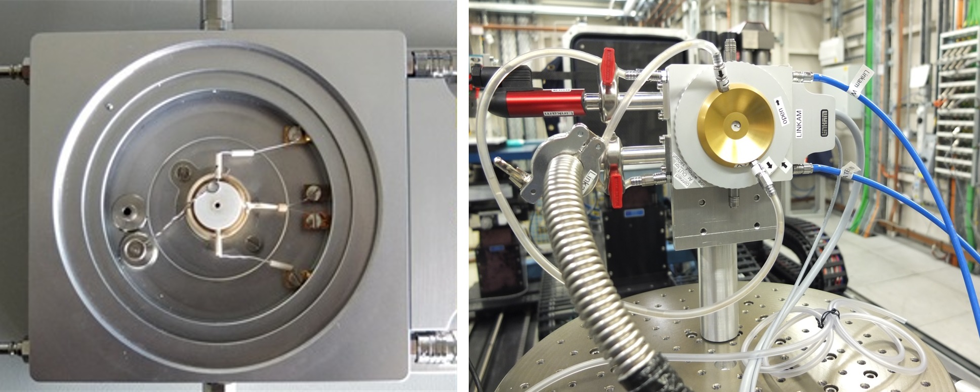
Linkam TS1500 hot stage: with ceramic sample cup (left) and mounted on the Sample Table in Experimental Hutch 1 (right).
The sample is placed inside the ceramic sample cup (~2.5-3 mm deep and 7 mm diameter) so that the sample is heated from the underneath as well as from the sides. A good sample to use is a 1 mm thick and ~ 6 mm in diameter with the total mass not exceeding 120 mg.
The total mass of sample and sample carrier above 120 mg will overload the heating element and equipment will not perform to specification or even the heating element can be damaged.
Maximal heating / cooling rate is 200 deg/min.
The Linkam TS1500 hot stage can be used only for diffraction experiments, it is not suitable for tomography measurements.
For more information about the Linkam TS1500 hot stage, please read the manual.
Important: The beamline cannot provide this stage if it was not requested in the proposal. The stage will be provided without vacuum pump if using with vacuum pump was not specified in the proposal.
Large electromagnet
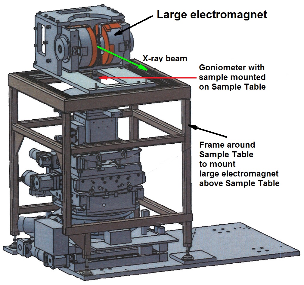
Schematic of large electromagnet installed on the frame above the Sample Table in Experimental Hutch 1.
Large electromagnet with remotely controlled magnetic field (in the range from 0 T to 1 T) can be installed above the Sample Table in Experimental Hutch 1. This electromagnet belongs to another beamline and can be used by special arrangement only. The installation of the large electromagnet is not a straightforward task and it requires 6-8 h from the users’ awarded beamtime.
Electromagnet can be used for both, diffraction and tomography measurements. It is installed on a specially designed frame above the sample Table, so the continuous tomography and 3D diffraction in the magnetic field are also possible.
CAD drawings of the large electromagnet (installed above Sample Table in Experimental Hutch 1) can be downloaded here.
Important: heating/cooling furnaces are not provided with this magnet and users are expected to design and bring the suitable furnace for work with this magnet. The beamline cannot provide the large electromagnet if it was not requested in the proposal.
INSTRON 3 kN Electro-Thermo-Mechanical Tester (ETMT)
The ETMT is owned by the University of Manchester at Harwell (UoMaH).
The use of this equipment for beamtime or offline work must be agreed with UoMaH ([email protected]) in advance of submitting a proposal.
Proposals are required to include a UoMaH staff member as co-investigator (after proposal acceptance at the latest).
All potential ETMT user will have to undergo a 2-day training course (day 1 provided by Instron (paid by the user), day 2 for familiarisation with the ETMT using own samples) ahead of any experiment. Access to I12 for ETMT training and/or ETMT familiarisation has to be coordinated with I12 staff.
Beamline staff will assist with installing the ETMT and preparing the beamline setup. They currently do not have the resources to train and support users in performing thermo-mechanical tests.
Experimental support for the use of the ETMT will be provided by UoMaH staff (normal working hours only).
If the ETMT is used in an experiment that results in a publication, the publication will reference The University of Manchester / Diamond collaboration in the following manner: "This experiment was possible due to the contribution of The University of Manchester at Harwell (UoMaH) ETMT".

Diamond Light Source is the UK's national synchrotron science facility, located at the Harwell Science and Innovation Campus in Oxfordshire.
Diamond Light Source Ltd
Diamond House
Harwell Science & Innovation Campus
Didcot
Oxfordshire
OX11 0DE
Copyright © Diamond Light Source. Diamond Light Source® and the Diamond logo are registered trademarks of Diamond Light Source Ltd
Registered in England and Wales at Diamond House, Harwell Science and Innovation Campus, Didcot, Oxfordshire, OX11 0DE, United Kingdom. Company number: 4375679. VAT number: 287 461 957. Economic Operators Registration and Identification (EORI) number: GB287461957003.