Instruments by Science Group
I12 Contact
Science Group Leader
Julia Parker
Email: [email protected]
Tel: +44 (0)1235 778924
I12 JEEP: Joint Engineering, Environment and Processing
Status: Operational
Beamsize: From 50 micrometer x 50 micrometer to 50 mm x 15 mm (EH1) or 100 mm x 30 mm (EH2)
Energy: 53 – 150 keV
Energy: 53 – 150 keV
Overview
Beamline I12 – JEEP offers experimental techniques for diffraction and imaging using monochromatic or polychromatic (white beam) X-rays.
The main advantages of Beamline I12 are:
- High energy X-rays (53-150 keV, monochromatic X-rays or energy-dispersive X-rays) for penetrating large or dense samples. The high photon energies and intensity make it possible to perform experiments on dense materials like engineering alloys and minerals. Samples can be larger, and more representative of bulk materials and processes.
- Large and configurable experimental stages for user-provided sample environments for in situ experiments. Various engineering and chemical processes can be studied using the users’ equipment, providing it fits on the beamline and the equipment is suitably designed for X-ray experiments. Equipment requiring long setup times can be prepared in Experimental Hutch 2, while another user group is performing experiments with the X-ray beam in Experimental Hutch 1.
- Combination of diffraction and imaging techniques on one sample in one experiment. Switching between monochromatic diffraction and imaging modes takes a few minutes, and is a popular mode of operation for I12 users.
Note: The diffraction and imaging measurements of the same sample are conducted sequentially rather than concurrently.
Monochromatic diffraction experiments on I12 include:
- Time-resolved and static monochromatic powder diffraction.
- Single-crystal diffraction using high-energy X-rays (e.g. for investigation of diffuse scattering).
- Total scattering on crystalline or amorphous materials (pair-distribution function analysis “PDF”). Note: DLS has a dedicated beamline for PDF: I15-1 and users should consider that beamline first.
Energy-dispersive diffraction experiments on I12 include:
- Strain mapping with selected gauge volume.
- Stroboscopic measurements on periodic processes such as rotating machinery.
- Measurements of diffraction patterns from samples confined in a large sample environment (e.g. electrochemical cells, large press, etc.)
Imaging experiments on I12 include:
- High-resolution radiography.
- High-speed radiography.
- High-resolution tomography (rotation up to 3 Hz, actual rotation speed depends on the required resolution and sample attenuation).
- High-speed tomography (rotation up to 8 Hz, actual rotation speed depends on the required resolution and sample attenuation).
- Tomography of large objects with Large Field of View (LFoV) camera assembly.
- Phase-contrast and phase-retrieval X-ray tomography in EH1.
Monochromatic powder diffraction
Beamline I12 offers time-resolved monochromatic powder diffraction techniques for different in situ applications:
- Phase transitions, crystallization, crystal growth, structure determination.
- High-resolution strain mapping.
- Texture development, crystalline alignment.
- Diffuse scattering from crystalline or amorphous materials.
Large 2D Area diffraction detector Pilatus3 X CdTe 2M is used for monochromatic powder diffraction. It can map a wide section through reciprocal space simultaneously, particularly at short wavelengths.
It is possible to vary the sample-detector distance and place the detector off-centre to optimise the setup for specific experiments. For further information, please read Large 2D Area diffraction detector.
Time-resolved monochromatic powder diffraction measurements can be combined in a series with other techniques (radiography, tomography, PDF) during one experiment. Please contact Beamline staff for evaluation of technical feasibility of your experiments before proposal submission, especially if you plan to use more than one technique in your experiment.
Caution: for ultra-high spatial resolution or reciprocal space resolution, other beamlines (offering longer X-ray wavelength) at DLS may be more suitable. Please consider that some organic and biological samples will scatter very weakly at the high photon energies used by I12. Some samples may not be stable in the intense X-ray beam.
Examples of time-resolved monochromatic powder diffraction experiments on Beamline I12:
1) Time-resolved in situ investigation of chemical reactions: ammonia-rich high-temperature superconducting intercalates of iron selenide revealed through time-resolved in situ X‑ray and neutron diffraction.
Advantages of I12: possibility to use complicated sample environment (provided by users) for synthesis, which cannot be performed in a small capillary; time-resolved measurements; high energy X-ray (for measurements in large container).
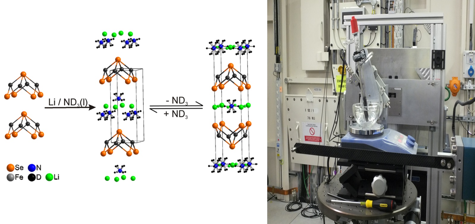
Investigated chemical process of the intercalation of lithium and ammonia into FeSe structure (left) and reaction cell on the Sample Table (right).
The intercalation of lithium and ammonia into the FeSe structure was investigated in situ by time-resolved X-ray powder diffraction. These measurements revealed the formation of high-temperature superconducting ammonia-rich intercalates of iron selenide, which reversibly absorb and desorb ammonia around ambient temperatures.
Reaction cell for in situ experiment was design by users. Preparation of ammonia-rich FeSe intercalates was performed in the beamline’s support laboratory, for which the users brought their own familiar laboratory equipment.
2) Time-resolved in situ investigation of microstrain during deformation: synchrotron X-ray diffraction study of in situ biaxial deformation.
Advantages of I12: possibility to use complicated sample environment (biaxial loading rig provided by users); time-resolved measurements; high energy X-ray (for measurements of dense steel samples).
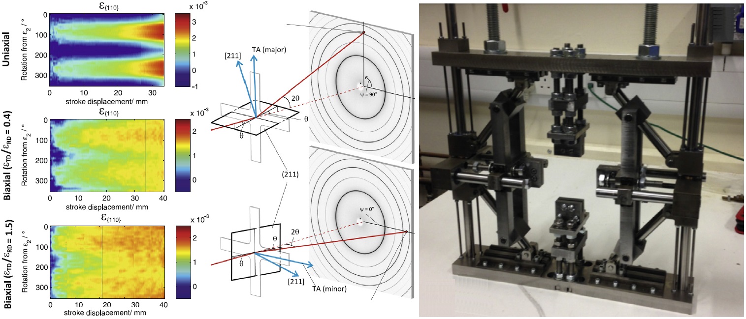
Microstrain evolution during dynamic uniaxial and biaxial loading (left); geometrical determination of the microstrain of selected reflections (middle) and biaxial loading mechanism designed for this experiment (right).
A biaxial loading mechanism was designed and built by users to enable deformation across the wide range of strain ratios. The Large Sample Table in EH2 on beamline I12 allowed movement of the whole experimental setup for measurements at different points of sample. This biaxial loading mechanism allowed the full diffraction rings to be acquired during arbitrary selected strain-paths, permitting lattice strains and reflection intensities to be measured across an unrivalled grain orientation range for such deformation conditions.
The deformation at three strain ratios of a single phase ferritic, low carbon steel has been studied including uniaxial, εTD = εRD = 0.4 biaxial deformation, and εTD = εRD = 1.5 (approximately balanced) biaxial deformation. The experiment revealed that the accumulation of lattice strain during deformation, as a function of azimuthal angle, is highly sensitive to strain path.
More information: D.M. Collins, M. Mostafavi, R.I. Todd, T. Connolley, A.J. Wilkinson. Acta Materialia. 2015. 90, 46–58.
3) Time-resolved in situ investigation of crystallization from solution: in situ observation of successive crystallizations and metastable intermediates in the formation of metal–organic frameworks.
Advantages of I12: possibility to use complicated sample environment for synthesis, which cannot be performed in a small capillary (ODISC furnace); time-resolved measurements; high energy X-ray (for measurements in large containers).
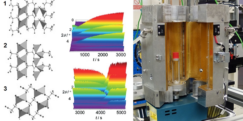
Investigated crystallization of lithium tartrate metal-organic frameworks (left) and reaction cell ODISC with reaction tube inside (right).
Understanding the crystallization of metal-organic frameworks (MOFs) is essential for the efficient design of new porous materials. Using high-energy in situ X-ray powder diffraction, the successive crystallization of lithium tartrate MOFs through three intermediate phases was observed. The high quality of data allowed solution of the crystal structures of intermediate phases from in situ powder diffraction data, as well as determination of rate constants and activation energies.
More information: H. H.-M. Yeung, Y. Wu, S. Henke, A.K. Cheetham, D. O’Hare, R.I. Walton. Angew. Chem. Int. Ed. 2016, 55, 2012–2016.
4) Time-resolved in situ investigation of crystallization from solution: in situ observation of successive crystallizations and metastable intermediates in the formation of cobalt gallate spinel photocatalyst.
Advantages of I12: possibility to use complicated sample environment for synthesis, which cannot be performed in a small capillary (ODISC furnace); time-resolved measurements; high energy X-ray (for measurements in large containers).
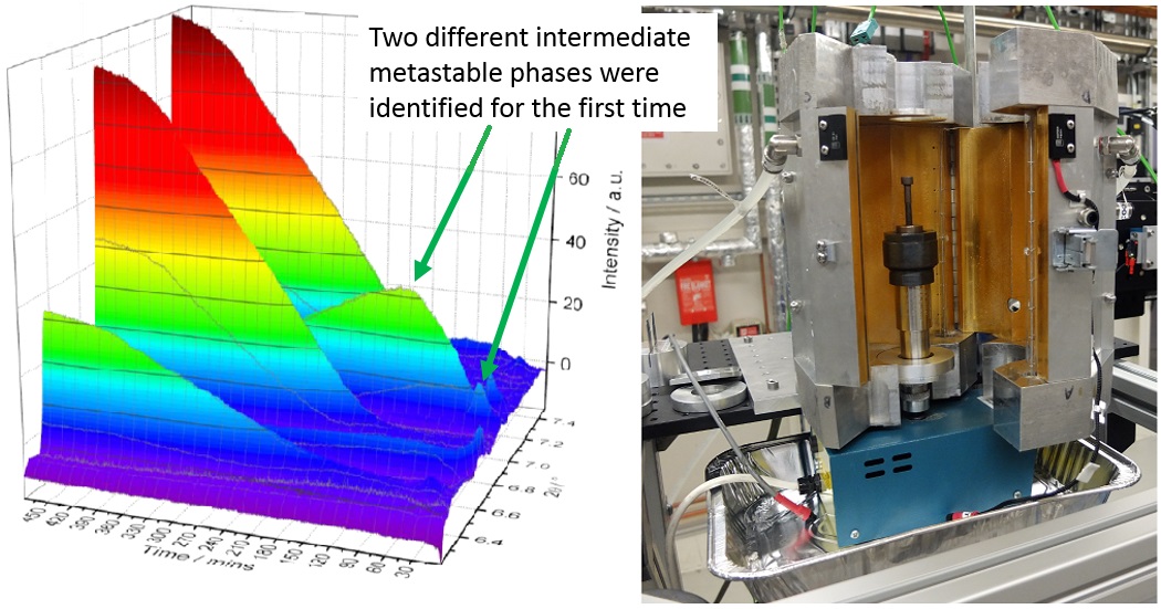
Crystallization of cobalt gallate spinel (left) and reaction cell ODISC with metal autoclave inside (right).
The aim of this experiment was to observe in situ the pathways of solvothermal crystallisation of cobalt gallate spinels to understand how the choice of synthesis parameters allows control of materials’ nanostructure by measuring the kinetic information from powder diffraction. For several reactions, two previously unknown intermediate metastable phases were identified and their crystal structures were characterized.
More information: D.S. Cook, Y. Wu, K. Lienau, R. Moré, R.J. Kashtiban, O.V. Magdysyuk, G.R. Patzke, R.I. Walton. Chemistry of Materials. 2017, 29, 5053–2057.
5) Time-resolved in situ investigation of phase transitions in solids: thermal behaviour of pharmaceuticals.
Advantages of I12: possibility to use complicated sample environment for analysing the thermal behaviour of materials or for the formation of new systems, which cannot be performed in a small capillary (Differential Scanning Calorimeter suitable for simultaneous transmission X-ray measurements and DSC measurements was provided by users); time-resolved measurements; high energy X-ray (for measurements in large containers).
![]()
Stabilization of metastable polymorph paracetamol III on heating (left) and DSC at Sample Table with labels showing DSC-cell in X-ray beam (right).
Simultaneous powder diffraction measurements and differential scanning calorimetry (DSC) measurements were performed for accurate characterisation of multiple polymorphic forms in different pharmaceutical crystals and co-crystal systems.
More information:
Energy-dispersive diffraction
Beamline I12 is unusual in offering time-resolved energy-dispersive (polychromatic) diffraction for various in situ applications:
1) In situ strain measurement and strain mapping.
2) Phase transitions, crystallization in sample environments too big or dense for monochromatic diffraction.
3) Stroboscopic diffraction of cyclic processes, such as rotating machinery
Energy-dispersive (polychromatic) diffraction on I12 is carried out using “white beam” X-rays with a custom-designed EDXD detector. It allows strain mapping or detailed investigation of structural transformations for samples in non-transparent metallic or ceramic environmental cells (electrochemical cells, batteries, autoclaves, etc.) or high-pressure cells.
The EDXD technique uses collimation of the incident and diffracted X-ray beams to form a gauge volume. Only diffracted X-rays from within the gauge volume are detected, enabling the EDXD technique to probe inside large, dense samples and sample environments.
To assist in setup and alignment, radiography with a small diagnostic camera is possible, using filtered white beam.
The EDXD technique can be used in combination with the beamline’s 100 kN servo-hydraulic loading rig for in situ strain measurements on samples undergoing deformation.
Caution: please note that due to the setup and alignment of the beamline optics, it is not recommended to combine EDXD with monochromatic imaging and diffraction techniques. If you have a requirement for combining EDXD with other techniques, please contact Beamline staff for evaluation of the technical feasibility of your combined experiments before proposal submission.
Examples of time-resolved energy-dispersive (polychromatic) diffraction experiments on Beamline I12:
1) Time-resolved in situ investigation of strain distribution: quantifying fatigue overload retardation mechanisms by energy-dispersive X-ray diffraction.
Advantages of I12: ability to perform an in situ mechanical test on an industry-standard crack growth test sample; time-resolved observation of strain field as crack propagated; high energy X-rays necessary to penetrate through a 10 mm thick sample; auxiliary use of white-beam radiography to assist in sample alignment.
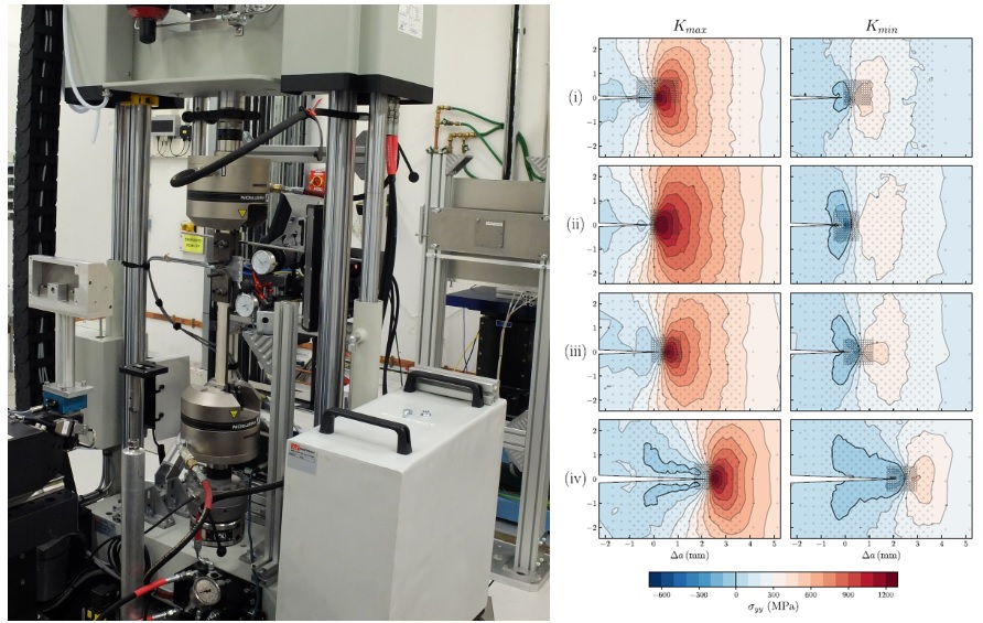
Left: sample installed in the INSTRON. Right: 2D stress maps measured at Kmax(LHS) and Kmin(RHS) at R = 0.4 for (i) one cycle before overload; (ii) at overload; (iii) when δa/rp = 0.3; and (iv) when δa/rp = 1.6. The light grey crosses indicate acquisition points. The thicker, black contour lines delineate 0 MPa.
The behaviour of propagating fatigue cracks after an overload event is still poorly understood, even after many years of study. The fatigue crack retardation mechanisms operating after an overload event were investigated for a bainitic steel using high spatial resolution energy-dispersive synchrotron X-ray diffraction. The elastic crack-tip strain fields were mapped at mid-thickness of compact tension samples at R-ratios of 0.1 and 0.4. The EDXD technique enabled mapping to be performed in a sample that was too thick (10 mm) for monochromatic diffraction. The beamline’s 100 kN servo-hydraulic rig was used to grow the fatigue crack in between strain mapping scans. The traction forces holding the crack faces open at minimum load were, for the first time, used to directly quantify the associated stress intensity factor, as a function of crack growth.
More information:
2) Time-resolved in situ investigation of chemical reactions: quantification of passivation layer growth in inert anodes for molten salt electrochemistry by in situ energy-dispersive diffraction.
Advantages of I12: ability to use a complicated and large sample environment provided by users (electrochemical cell); the gauge volume allowed recording of a clean signal from the sample deep within the sample environment; only signal from the sample was recorded, and all signals from container were ignored due to collimator geometry; time-resolved measurements; high energy X-ray (for measurements in large containers).
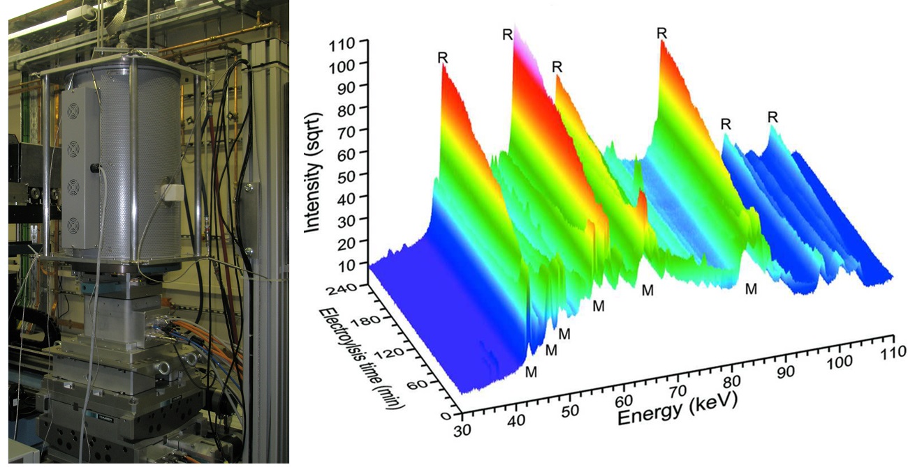
Electrochemical cell used for experiment (left) and results of in situ investigation of electrolysis reaction (right; M – Magneli phase, R – Rutile phase).
Reaction cell for in situ experiment was design by users. An in situ energy-dispersive X-ray diffraction experiment was undertaken on operational titanium electrowinning cells to observe the formation of rutile (TiO2) passivation layers on Magneli-phase (TinO2n-1; n = 4–6) anodes and thus determine the relationship between passivation layer formation and electrolysis time. Quantitative phase analysis of the energy-dispersive data was undertaken using a crystal-structure-based Rietveld refinement. Layer formation was successfully observed and it was found that the rate of increase in layer thickness decreased with time, rather than remaining constant as observed in previous studies. The limiting step in rutile formation is thought to be the rate of solid state diffusion of oxygen within the anode structure. Despite the small amount of sample in the large electrowinning cells, only signal from the sample was recorded, and no peaks from the container were observed.
More information:
3) Time-resolved in situ stroboscopic measurements during periodic processes: time-resolved in situ investigation of dynamic internal microstrain in the rotating piece of machinery using synchrotron X-rays.
Advantages of I12: possibility to perform an experiment complicated rig provided by the users; synchronisation of diffraction data collection with a cyclic process in a stroboscopic technique; combination with white-beam high-speed radiography.
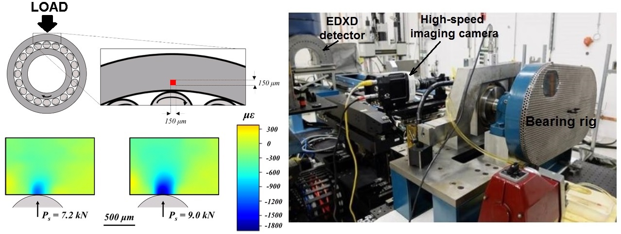
Projection of the gauge volume in the yz-plane position of the outer raceway, relative to the rolling element and radial load application. The centre of the gauge volume was 250 μm into the subsurface, within a region plastically deformed from pre-overloading (left top); two-dimensional subsurface radial stain maps (left bottom); bearing rig installed on the beamline (right).
Using an intense and highly penetrating white X-ray beam and an energy-dispersive detector allowed measurements of the X-rays diffraction from deep within rotating bearings. Due to the fast rotation of the bearing balls, the ball in the correct position was for about 2 milliseconds only, and so the X-ray counts for one cycle were not enough for acceptable data analysis. By adding up the signal collected at the same point in the cycle over many cycles, a dataset that could be analysed was obtained. This ability to “freeze frame” and sum the data collection over repeated cycles is why this is known as a stroboscopic technique. A high-speed X-ray imaging camera enabled to confirm visually, during setup, that the ball was indeed in the right place when the gating signal was sent.
4) Time-resolved in situ investigation of chemical reactions: following the electroreduction of uranium dioxide to uranium in LiCl–KCl eutectic in situ using synchrotron radiation.
Advantages of I12: possibility to use complicated and large sample environment provided by users (electrochemical cell) for combined electrochemical measurements and in situ diffraction; time-resolved measurements; only signal from the sample was recorder using energy-dispersive diffraction, and almost all unwanted signal from the container was eliminated due to the collimator geometry; high energy X-ray (for measurements in large containers).
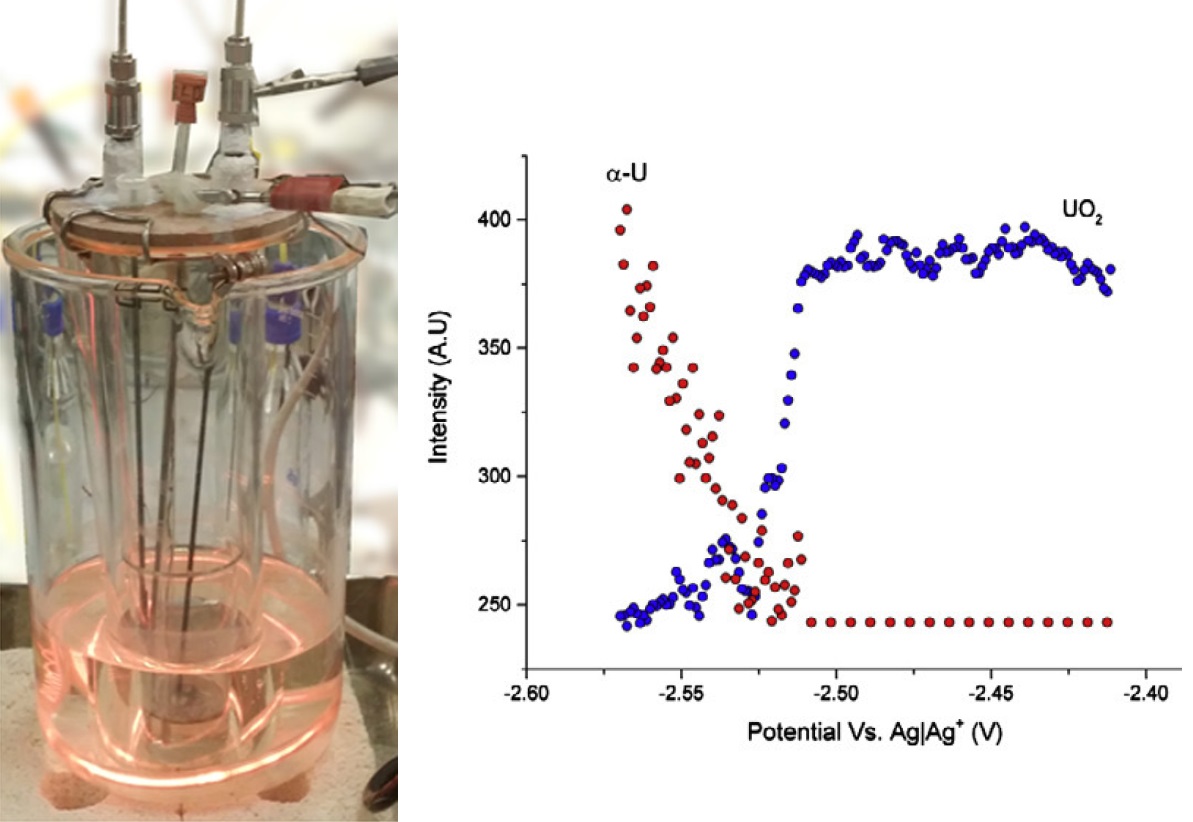
Electrochemical cell used for experiment (left) and results of in situ investigation of electrochemical reduction (right).
For the first time, the electrochemical reduction of uranium dioxide to metallic uranium was investigated in lithium chloride–potassium chloride eutectic molten salt at 450°C with a purpose to deduce the reduction pathway. No intermediate phases during electro-reduction process of α-uranium formation were identified using the X-ray diffraction. This suggests that the electrochemical reduction occurs via a single four-electron transfer process at a more positive potential than the potential for Li deposition from the electrolyte.
More information:
5) Time-resolved in situ stroboscopic measurements during periodic processes: time-resolved in situ investigation of dynamic internal microstrain in the working combustion engine using synchrotron X-rays.
Advantages of I12: possibility to perform an experiment on a complete piece of machinery provided by the users; synchronisation of diffraction data collection with a cyclic process in a stroboscopic technique; combination with white-beam high-speed radiography.
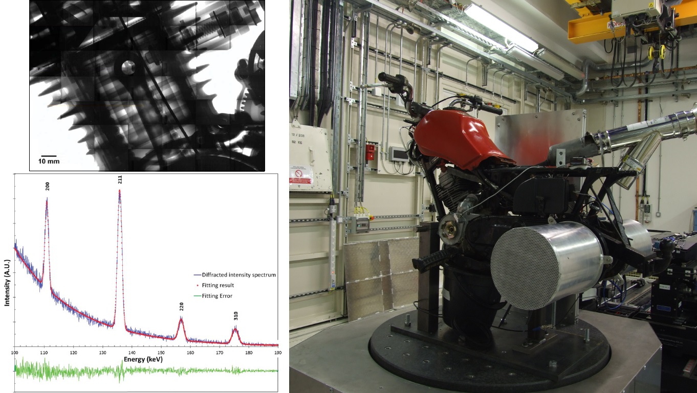
Engine cross-section assembly close to 0° crankshaft rotation measured with imaging detector (top left); diffraction measurements of live point of the engine assembly cross section at 2000 rpm measured with EDXD detector (bottom left); experimental setup of engine on Large Sample Table in Experimental Hutch 2 (right).
The unique capabilities of Experimental Hutch 2 (EH2) for large samples and samples sample environments were used to record X-ray movies of a motorcycle internal combustion engine running at 1850 r.p.m. and to measure strain inside the connecting rod via energy-dispersive X-ray diffraction measurement. The high penetrating ability and high flux of the X-ray beam at I12 allowed the observation of inlet and outlet valve motion, as well as that of the piston, connecting rod and the timing chain within the engine. Finally, the dynamic internal strain within the moving connecting rod was evaluated with an accuracy of ~ 50 × 10-6.
More information:
Imaging
Structural integrity and structural changes in bulk samples can be imaged in a non-destructive way with X-ray transmission radiography. When monochromatic X-rays are used, this results in two-dimensional projections whose contrast represents electron-density differences within the object. For tomography, a set of such projections taken at different orientations can be processed by a computer to reconstruct the three-dimensional density distribution.
The method is of great interest in applied Material Science and Engineering because it allows the study of various features within bulk samples, such as cracks, pores, precipitates, and phases of different compositon. By using specially-constructed sample cells, in-service conditions such as load or temperature can be simulated. The short image acquisition times possible with synchrotron radiation mean that changes in samples over time can be recorded. If the high intensity "white beam" is used, very short exposure times can be used to record dynamic processes.
The partial coherence of the X-ray beam from a synchrotron source can be used in a phase contrast technique to enhance the interfaces between different materials whose X-ray absorption is similar.
Engineering and Material Science Applications
-
Creep-fatigue interaction during high temperature cycling.
-
Damage and failure investigation.
-
Defect evolution during loading.
-
Thermo-mechanical fatigue or corrosion fatigue.
-
3D imaging of complex materials such as metallic foams and composites.
Chemical Engineering Applications
-
Imaging of flow.
-
Mixing in complex fluids.
-
Powder flow processes and compaction.
Earth and Environmental Science Applications
-
Radiographic imaging.
Biomedical Imaging Applications
-
Three-dimensional quantification of mineral contents in bone and teeth.
-
Mechanical behaviour of bone under load.
-
Diffusion processes in dentine.
-
Interface structure between implant and tissue.
-
Phase contrast imaging of soft tissue.
Examples of imaging experiments on Beamline I12:
1) Time-resolved in situ investigation of alloy solidification in high magnetic fields: synchrotron X-ray high-resolution tomography study of microstructure during controlled alloy solidification in high magnetic fields.
Advantages of I12: possibility to use complicated sample environment (Large electromagnet); time-resolved continuous measurements (10 sec per tomography); high energy X-ray (for measurements of dense alloy samples).
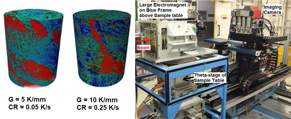
The formation of screw structure in alloy under high magnetic field (0.5 T) at different temperature gradients (G) and cooling rates (CR) (left); Large Electromagnet installed on the Blue Frame above the Sample Table (right).
A special furnace for directional solidification was designed and built by users to enable the high-resolution tomographic investigation of solidifying micro- and macro-structure under the influence of variable magnetic field. The Blue Frame around Sample Table in EH1 allowed installation of heavy (ca. 200 kg) Large Electromagnet above the rotating Theta-stage to enable tomography measurements.
More information: B. Cai, A. Kao, O.V. Magdysyuk, R.C. Atwood, N.T. Vo, K. Pericleous, P.D. Lee. Acta Materialia. 2020. 196, 200–209
2) Time-resolved in situ high-speed radiography of additive manufacturing: synchrotron X-ray high-speed radiography study of the behaviour of the liquid metal and formation of the solid track during laser-based "3D Printing" of metallic alloys.
Advantages of I12: possibility to use complicated sample environment provided by users; the high flux allows radiographic imaging to be carried out at a time scale sufficient to resolve the circulation in the melt pool, bubble formation, and droplet ejection during the process; monochromatic X-rays allow sufficient contrast among the solid phases and the liquid phase; high-speed camera and optical modules allow capture of the radiographic image, rates of up 10,000 frames per second have proven useful with this device and material
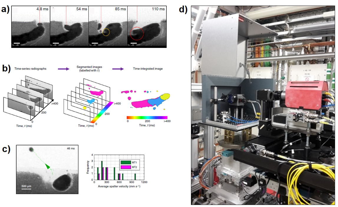
a) Some defects forming during a second layer of powder melting; b) evolution of the 3-d printed track over 400 milliseconds obtained by computational image analysis of the video frames; c) analysis of the droplets ejected – these can result in poor quality as they lodge on the finished material; d) User’s bespoke in-situ equipment laser additive manufacturing installed in I12-EH1 with its own interlocked cabinet. The cabinet is open (raised grey cover) revealing the laser optics and printing chamber, all mounted on the Sample Table of EH1 with 400mm optical bread-board interface.
On the scale of milliseconds, the various processes taking place could be observed and related to the types of defects that are found in laser-printed metal items. Observing the process in situ allows the understanding that is not easily obtained only by analysis of the final item.
More information: C.L.A. Leung, S. Marussi, R.C. Atwood, M. Towrie, P.J. Withers, P.D. Lee. Nature Comm. 2018. 9, 1355
Combined experimental techniques
Beamline I12 offers the combination of a few experimental techniques applied in a series (not simultaneously) on the same sample.
Please, read carefully the description of the Beamline, various Techniques and Detectors before applying for a beamtime.
Please contact Beamline Staff for evaluation of technical feasibility of your experiments before proposal submission if you plan to use more than one technique in your experiment.
Caution: for ultra-high spatial resolution or reciprocal space resolution, other beamlines (offering longer X-ray wavelength) at DLS may be more suitable. Please consider that some organic and biological samples will scatter very weakly at the high photon energies used by I12. Some samples may not be stable in the intense X-ray beam.
Examples of time-resolved monochromatic powder diffraction and monochromatic high-resolution tomography experiments on Beamline I12:
1) In situ investigation of the strain as a function of applied load: fracture tests on the metal-matrix composite double edge notch tension samples.
Advantages of I12: possibility to perform an in situ mechanical test on an industry-standard crack growth test sample; possibility to use complicated sample environment (10 kN Shimadzu loading rig provided by users); possibility to accommodate large and heavy user’s equipment in Experimental Hutch 2; high energy X-rays necessary to penetrate through a 5 mm thick sample; time-resolved observation of strain field as crack propagated using the monochromatic X-ray diffraction; monochromatic X-ray computed tomography for digital volume correlation.
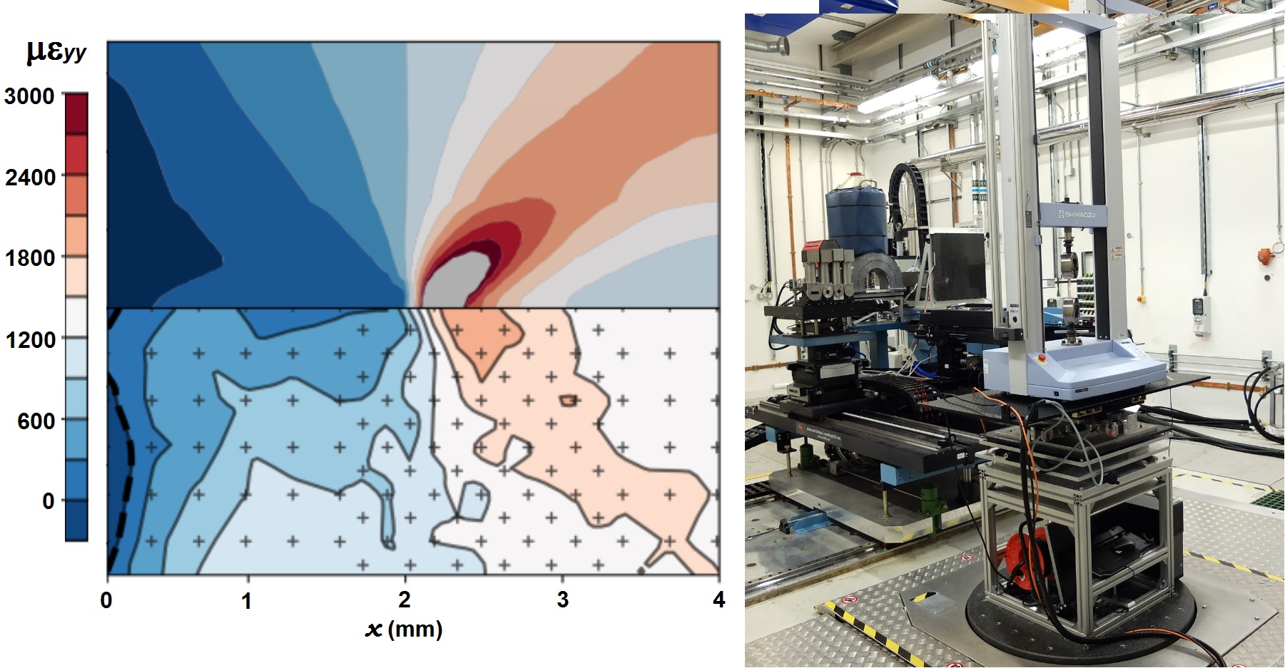
A comparison between the modelled (top) and experimental (bottom) full field elastic strain, εyy at a/W = 0.5 (left); rig used for this experiment with imaging camera and diffraction detector installed in Experimental Hutch 2 (right).
Monochromatic synchrotron X-ray diffraction and monochromatic synchrotron X-ray computed tomography were used to measure elastic strain and total strain respectively. The measured elastic strains in the samples are detailed as a function of applied load and compared against those predicted from a 3D elastic-plastic finite element model.
More information: C.A. Simpson, S. Tonge, T Connolley, C. Reinhard, T.J. Marrow, M. Mostafavi Theoretical and Applied Fracture Mechanics. 2019. 102281.
2) In situ investigation of elastic and total strains as a function of applied load: direct measurements of the elastic and total strains in the polygranular synthetic nuclear graphite.
Advantages of I12: possibility to perform an in situ mechanical test on the real-size sample; possibility to use complicated sample environment (10 kN Shimadzu loading rig provided by users); possibility to accommodate large and heavy user’s equipment in Experimental Hutch 2; possibility to install additional user’s equipment (DIC); high energy X-rays necessary to penetrate through a 10 mm thick sample; monochromatic X-ray diffraction for elastic strain measurements; monochromatic X-ray computed tomography for total strain measurements by digital volume correlation.
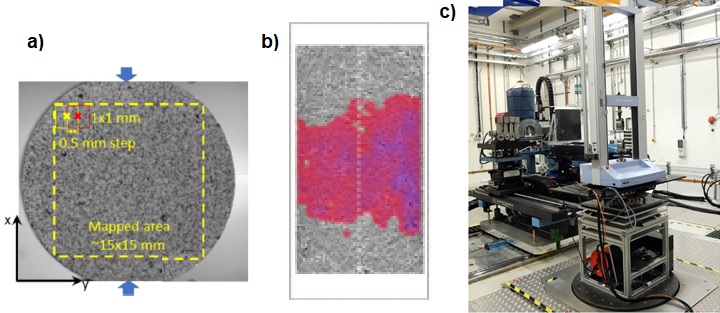
a) The area mapped by X-ray diffraction; b) example of the 3D strain measured by digital volume correlation of tomographs; c) rig used for this experiment with imaging camera and diffraction detector installed in Experimental Hutch 2.
In situ synchrotron monochromatic X-ray diffraction, combined with image correlation analysis of 2D optical and 3D X-ray tomography datasets allowed investigation of the relation between elastic lattice strain and total strain during deformation of Gilsocarbon polygranular nuclear grade graphite. synchrotron X-ray diffraction and monochromatic synchrotron X-ray computed tomography were used to measure elastic strain and total strain respectively. The measured elastic strains in the samples are detailed as a function of applied load and compared against those predicted from a 3D elastic-plastic finite element model.
More information: D. Liu, T. Zillhardt, P. Earp, S. Kabra, T. Connolley, T. J. Marrow. Carbon. 2020. 163, 308-323.
3) In situ study of the damage mechanism under high temperature and high cycling fatigue: direct measurements of the strain around the crack with monochromatic X-ray diffraction and 3D visualisation of the crack propagation with monochromatic X-ray tomography.
Advantages of I12: possibility to perform an in situ mechanical test on the real-size sample; possibility to use complicated sample environment (Deben-Manchester open frame rig provided by users); high energy X-rays necessary to penetrate through a 1-2 mm thick samples; monochromatic X-ray diffraction for elastic strain measurements; monochromatic X-ray computed tomography for 3D visualisation of crack propagation.
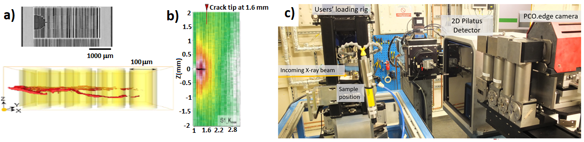
a) Morphology of the crack from tomogrpahy measurements; b) variation in the relative elastic strain along the fibresas a function of load and position; c) experimental setup in Experimental Hutch 1.
The damage accumulation and load partitioning mechanisms of TC17 titanium alloy/SiC fibre composites at a temperature 350 oC (representative of likely in-service aeroengine environments) have been investigated by visualising the 3D damage morphology (by X-ray tomography) and strain mapping (by X-ray diffraction) in the stable (=fibre bridging) and rapid (=fibre fracture) growth regimes.

Diamond Light Source is the UK's national synchrotron science facility, located at the Harwell Science and Innovation Campus in Oxfordshire.
Diamond Light Source Ltd
Diamond House
Harwell Science & Innovation Campus
Didcot
Oxfordshire
OX11 0DE
Copyright © Diamond Light Source. Diamond Light Source® and the Diamond logo are registered trademarks of Diamond Light Source Ltd
Registered in England and Wales at Diamond House, Harwell Science and Innovation Campus, Didcot, Oxfordshire, OX11 0DE, United Kingdom. Company number: 4375679. VAT number: 287 461 957. Economic Operators Registration and Identification (EORI) number: GB287461957003.