Instruments by Science Group
I12 Contact
Science Group Leader
Julia Parker
Email: [email protected]
Tel: +44 (0)1235 778924
I12 JEEP: Joint Engineering, Environment and Processing
Status: Operational
Beamsize: From 50 micrometer x 50 micrometer to 50 mm x 15 mm (EH1) or 100 mm x 30 mm (EH2)
Energy: 53 – 150 keV
Energy: 53 – 150 keV
| Distance from sample to source: | 51 m |
| Maximum beam size: | ~ 50 mm horizontally and ~ 13 mm vertically |
| Hutch dimensions: | 9 m long × 5 m wide × 3 m high (clear) |
| Sample Table: | Suitable for tomography and diffraction |
| Sample Table capacity: | 50 kg (option of 200 kg with limited functionality) |
| Overhead crane capacity: | 1000 kg |
Experimental Hutch 1 (EH1) Layout
- EH1 Sample Table (for samples and sample environments)
- EH1 Large Detector Table with four modules M1, M2, M3, and M4 (for detectors, imaging cameras, and additional equipment)
- EH1 Small Detector Table (for detectors and imaging cameras)
- EH1 Optics Table (for additional instruments to go before sample)
- EH1 Additional Equipment (power, cooling water, pressurised gases, manual crane, cable chicanes, signalling from and to beamline)
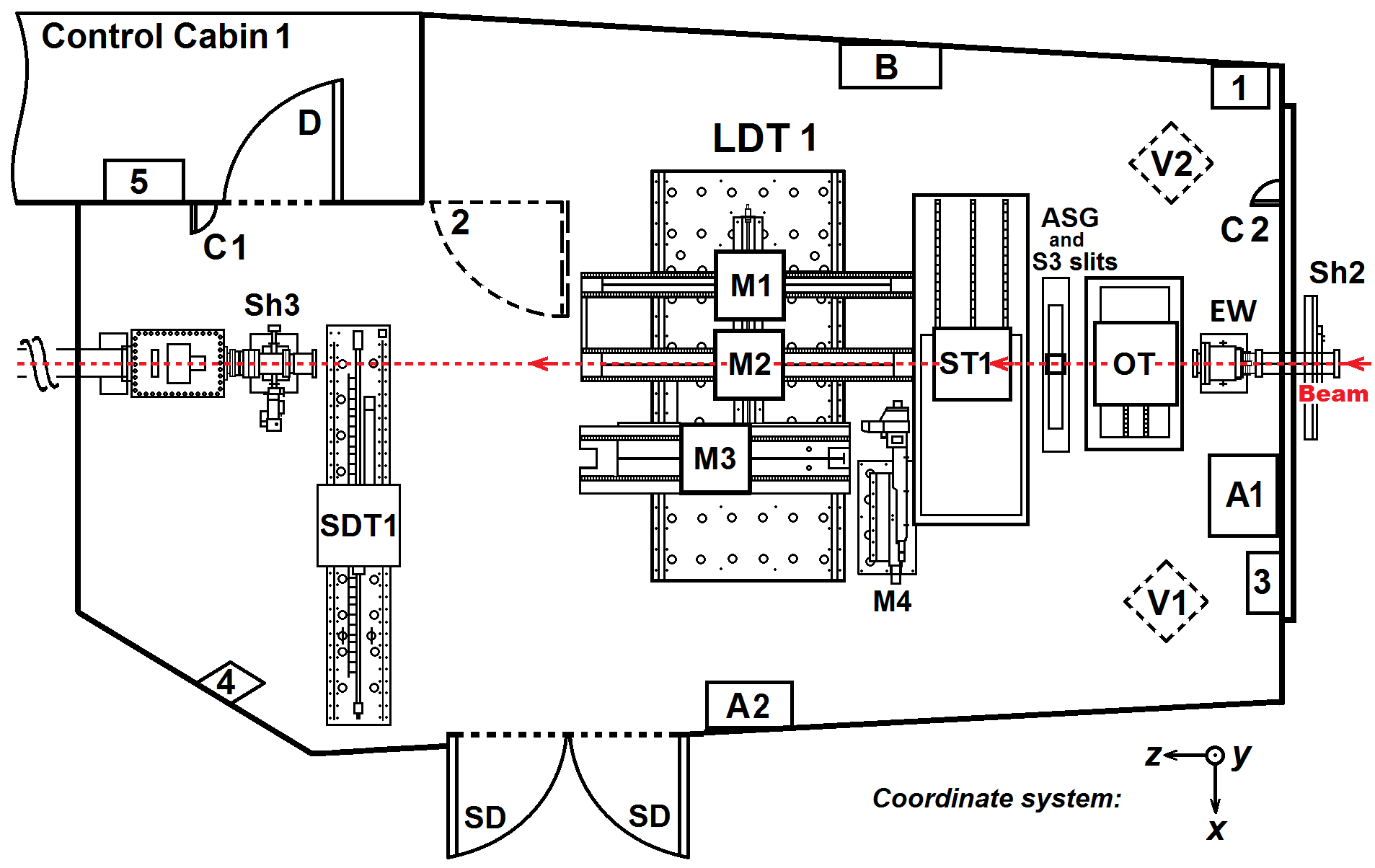
Schematic of Experimental Hutch 1 (EH1):
- Red dashed line - X-ray beam direction.
- Numbers 1, 2, 3, 4, 5 – series of search buttons and gates, which should be activated in a sequence during search procedure for taking beam.
- Sh2 – second shutter for beam into EH1.
- EW – beam Entry Window.
- OT – Optics Table.
- ASG and S3 slits – Anti-Scatter Guard and remotely controlled clean-up S3 slits for imaging and diffraction.
- ST1 – Sample Table 1.
- LDT1 – Large Detector Table 1 with four modules M1, M2, M3, and M4, where M1 – module 1 for imaging camera, M2 – module 2 for large area 2D detector, M3 – module 3 for custom detectors and cameras, M4 – module 4 for beamstop or special instruments.
- SDT1 – Small Detector Table 1.
- Sh3 – third shutter, exit of beam from EH1 to External Building.
- A1 – standard and high-current single phase power supply and Ethernet connections.
- A2 – high-current three phase power supply.
- B – pressurized gas supplies.
- C1 – downstream cable chicane to Control Cabin 1.
- C2 – upstream cable chicane to CIA (allows receiving/sending analogue and digital signals between beamline and user equipment) and to corridor.
- D – door to Control Cabin 1.
- SD – Service Doors to periferal labs and for large equipment.
- V1 – first point of downstream view of EH1 (image below).
- V2 – second point of downstream view of EH1 (image below).
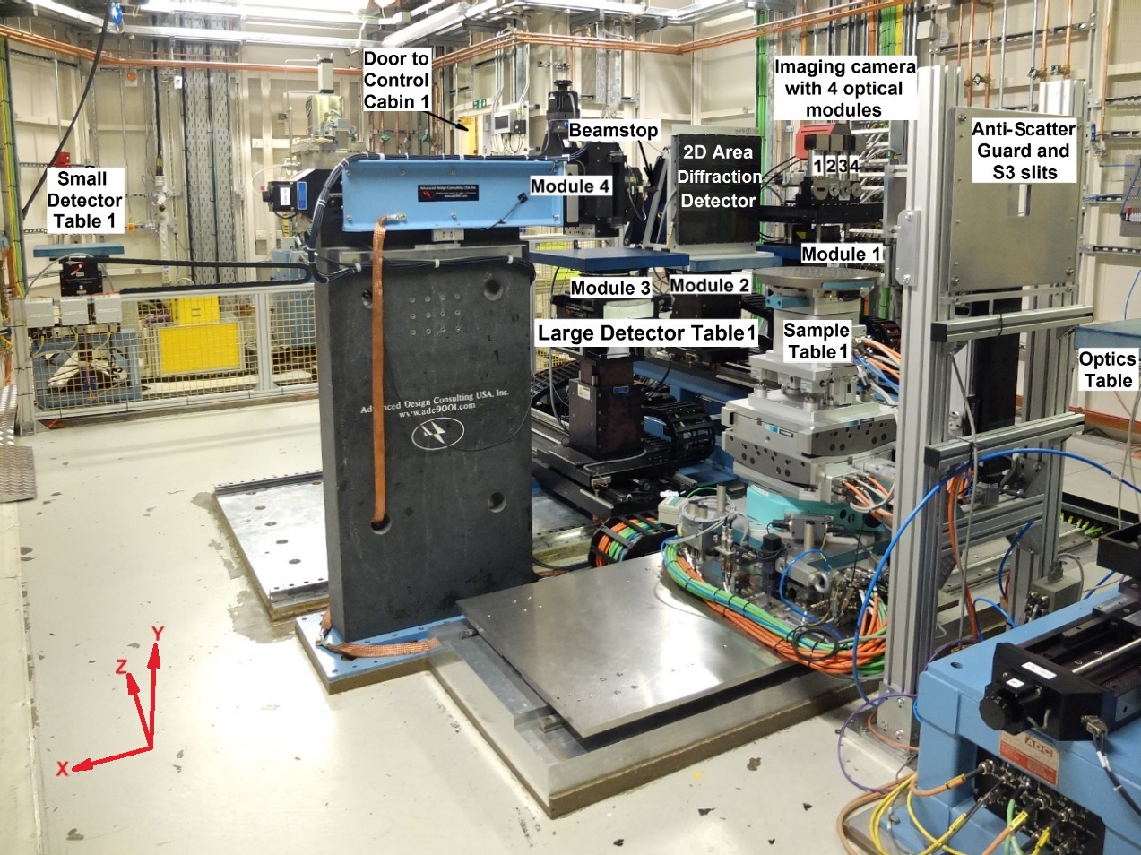
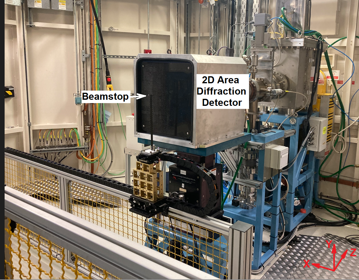
Downstream view of EH1 (first view point V1 on EH1 schematic above) with xyz-coordinate system; z-axis is along the beam direction, y-axis is vertical, x-axis is horizontal perpendicular to the beam direction. Optics Table; Anti-Scatter Guard and S3 slits; Sample Table 1; Large Detector Table 1 with remotely controlled Module 1 (with imaging camera employing 4 optical modules numerated 1, 2, 3, and 4), Module 2 (with 2D Area diffraction detector), Module 3 (empty, any detector or camera can be placed), and Module 4 (with beamstop mounted, any small instrument can be mounted instead); Small Detector Table 1 in outer position (empty, any detector or camera can be placed).
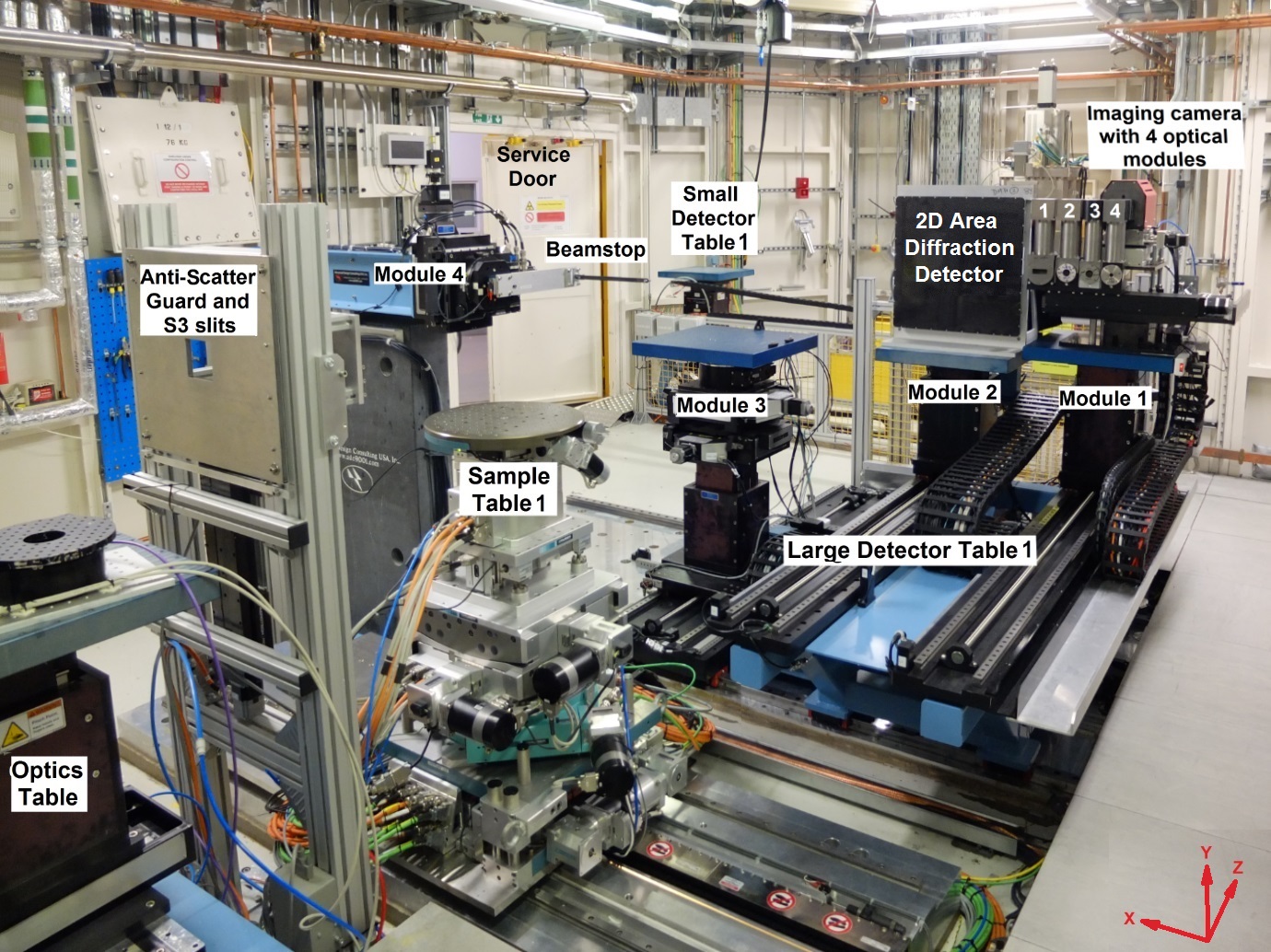
Downstream view of EH1 (second view point V2 on EH1 schematic above) with xyz-coordinate system; z-axis is along the beam direction, y-axis is vertical, x-axis is horizontal perpendicular to the beam direction. Optics Table; Anti-Scatter Guard and S3 slits; Sample Table 1; Large Detector Table 1 with remotely controlled Module 1 (with imaging camera employing 4 optical modules numerated 1, 2, 3, and 4), Module 2 (with 2D Area diffraction detector), Module 3 (empty, any detector or camera can be placed), and Module 4 (with beamstop mounted, any small instrument can be mounted instead); Small Detector Table 1 in outer position (empty, any detector or camera can be placed).
More detailed drawings of EH1 (incl. CAD models) are available upon request from the I12 Beamline staff.
Sample Table 1 (ST1)
1. Technical description of Sample Table 1
Sample Table 1 can accommodate a variety of different samples and sample environments. In full configuration, it can accommodate weight of 50 kg, allowing diffraction, radiography, and tomography experiments. Removing the top tomography stage of Sample Table 1 permits accommodation of samples and sample environments with a weight up to 200 kg and allows diffraction and radiography experiments only.
Sample Table 1 has up to 10 degrees of freedom of motion, and different combinations of motion can be set up. During tomography experiments, some axes are needed to align the sample table and to carry out automated motions. Then, these axes are not available for other purposes and thus the number of degrees of freedom to the sample is limited.
Sample Table 1 can also be considered as a motorised goniometer allowing rotation of the sample along three Eulerian angles. This facilitates single crystal diffraction at beamline I12.
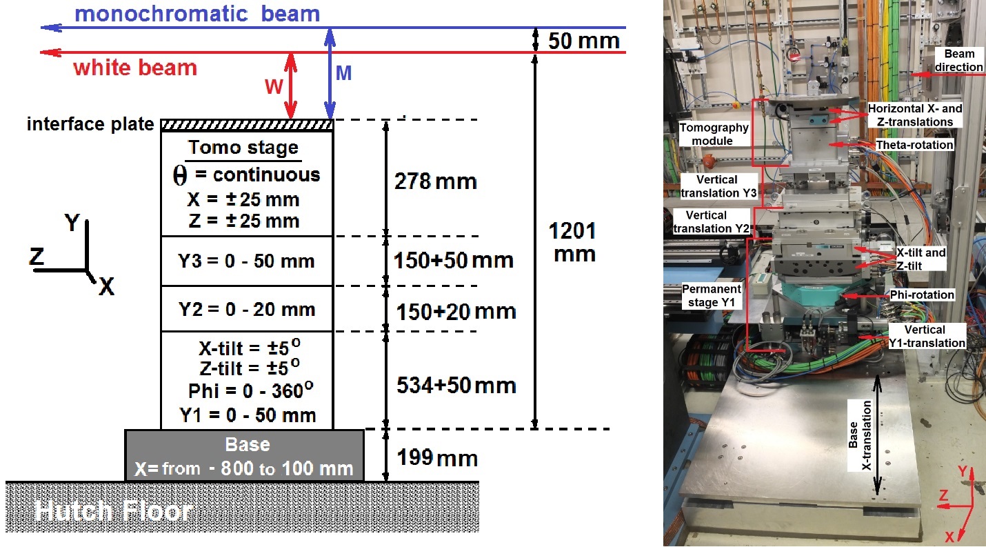
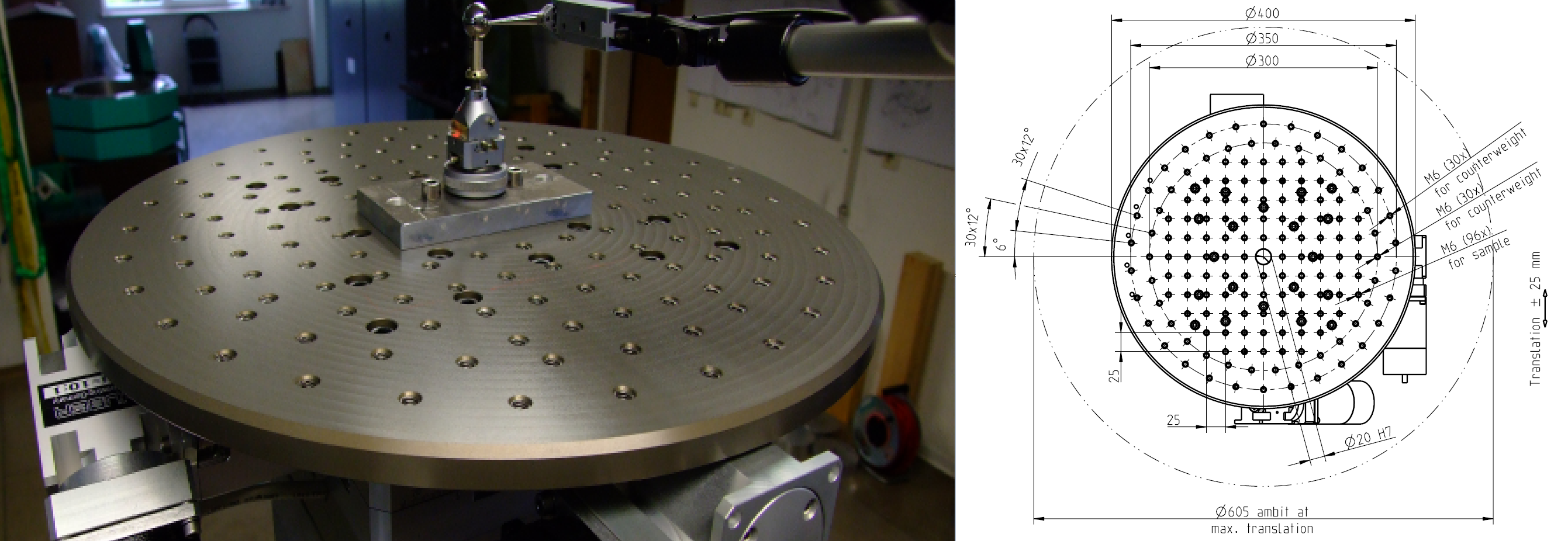
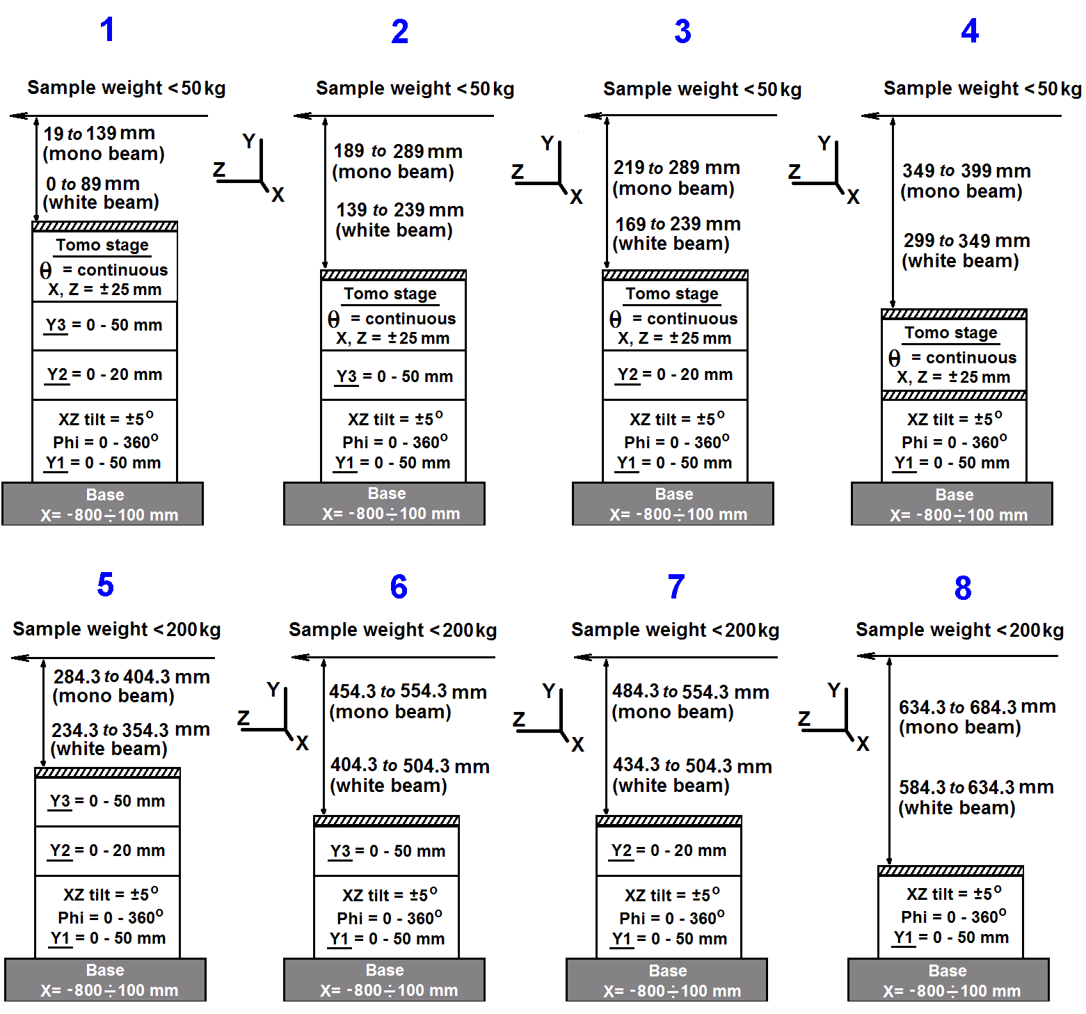
Schematic of Sample Table 1 showing all available motions and photo of Sample Table 1. M - distance between interface plate and monochromatic beam, W - distance between interface plate and white beam.
| Modules of Sample Table 1 | Movement and Comments |
|
Interface plate |
Interface plates of different thickness (25 mm pitch, M6). |
| Tomography module |
Horizontal X- and Z-translations: ± 25 mm - sample positioning and scanning for tomography and diffraction. Theta-rotation: continuous - continuous sample rotation. Has a centred square array of M6 tapped holes at 25 mm pitch. Always removed for samples > 50 kg and present for samples < 50 kg. |
| Vertical translation Y3 |
Vertical Y-translation: 0 - 50 mm - vertical fine motion for sample positioning and scanning for tomography and diffraction. Can be removed for large samples and sample environment. |
| Vertical translation Y2 |
Vertical Y-translation: 0 - 20 mm - vertical fine motion for scanning sample through beam. Can be removed for large samples and sample environment. |
| Permanent Stage Y1 |
Vertical Y-translation: 0 - 50 mm - vertical motion for switching between white and monochromatic modes. Can be used for rough vertical positioning. Phi-rotation: 0 - 360° - slow complete rotation from 0 to 360° for experiments. X-tilt and Z-tilt: ± 5° - tilts for alignment of samples for diffraction experiments or for alignment of virtual rotation axis for tomography. |
| Base |
X-translation: -800 ÷ 100 mm - moving stage in/out beam. |
2. Experimental arrangement of Sample Table 1
Please, consider making support plate of your equipment comparable with I12 Sample Table interface to avoid mounting problems during installation of your equipment:
- If Tomography module remains on the Sample Table 1 (configurations 1-4 on the scheme below), please use the drawing of Tomography module plate.
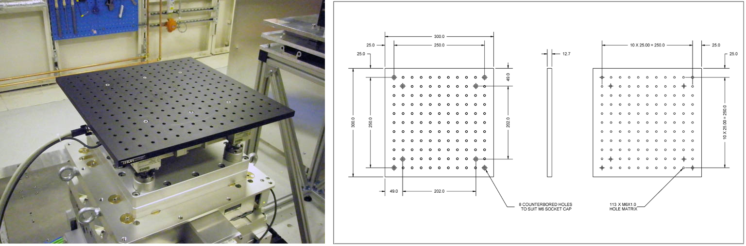
- If Tomography module is removed from the Sample Table 1 (configurations 5-8 on the scheme below), please use the drawing of interface plate.
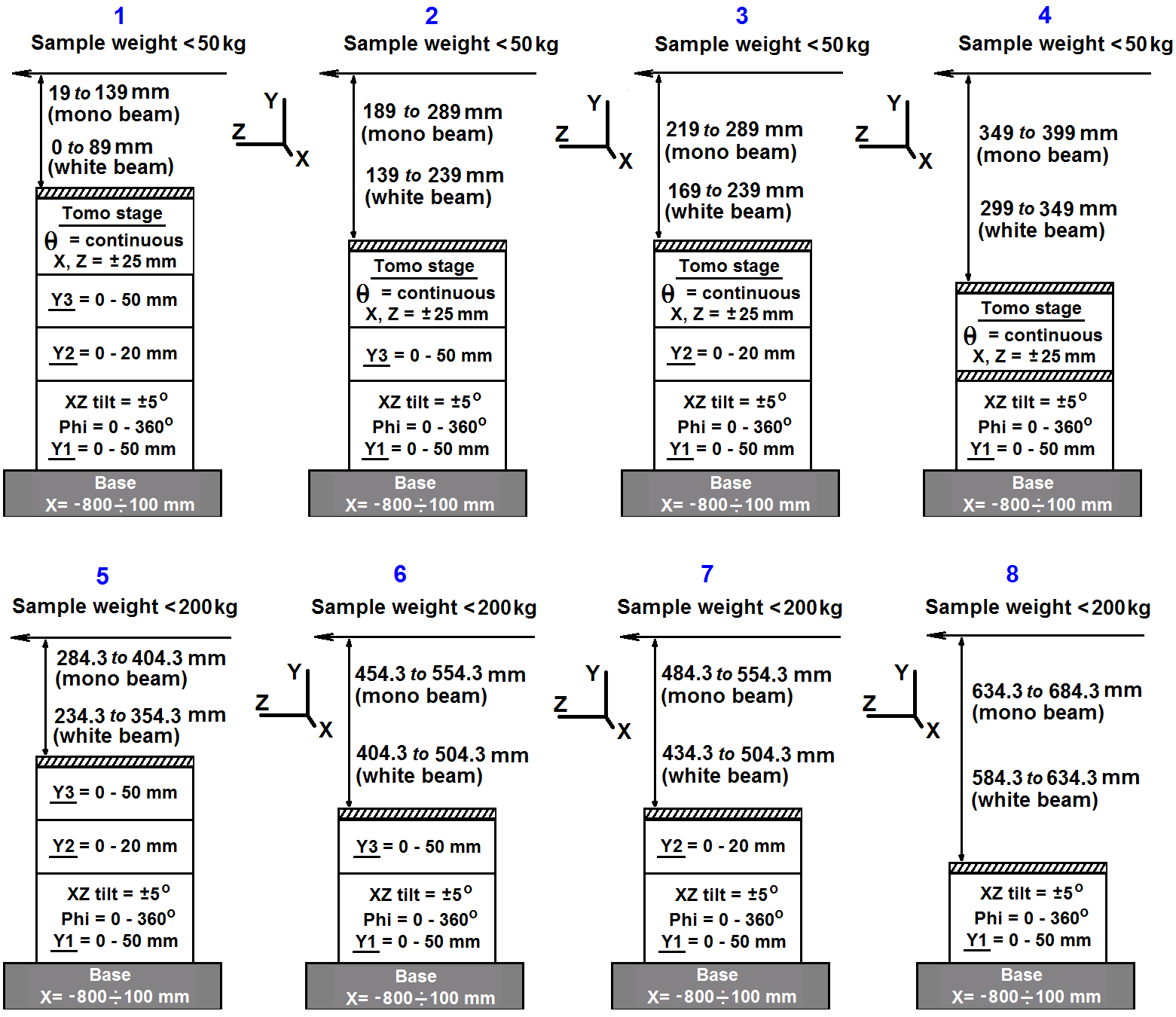
Possible configurations of Sample Table in EH1 with distances (in mm) from top interface plate to white and monochromatic beam. Your sample need to have a height between presented values for exposing by X-rays. Sample > 50 kg will not have top translation or rotation available.
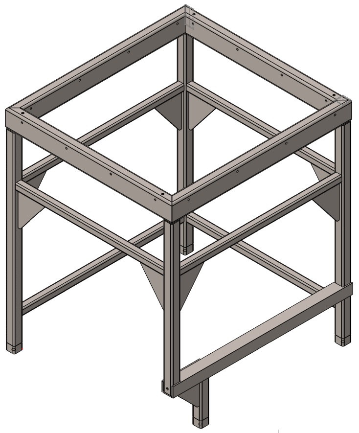
The heavy-duty Blue Frame can be placed around the Sample Table in EH 1 to accommodate the user’s the equipment which is heavier than 50 kg and allow tomo-stage to remain installed. When Blue Frame is installed around the Sample Table 1, only configurations 2 (tomo-stage + Y3 + Y1), 3 (tomo-stage + Y2 + Y1), and 4 (tomo-stage + Y1) are allowed, while configuration 1 is not permitted due to height limitations. The heavy user’s equipment can be installed on the Blue Frame and remain stationary, while sample can be installed on the rotation tomo-stage for tomography and/or diffraction measurements.
Download schematic of the heavy-duty Blue Frame or corresponding STEP-file in zip-achive.
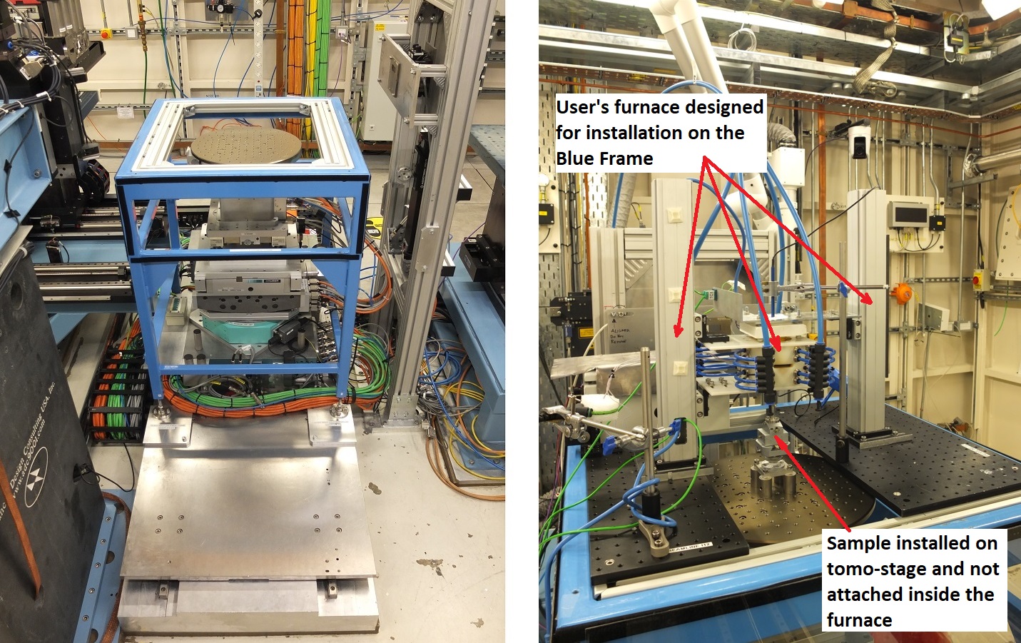
View of the heavy-duty Blue Frame around the Sample Table in EH1 from the side and example of installation of user's equipment on the Blue Frame. Sample Table 1 has configuration 2 (tomo-stage + Y3 + Y1).
Sample Table 1 can be considered as a goniometer of a diffractometer, allowing rotation of sample along three Eulerian angles, making possible single crystal diffraction at beamline I12.
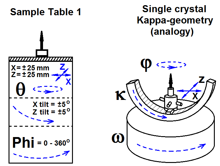
Single crystal diffraction using Sample Table 1. The relation to the traditional single crystal diffractometer is given on the right side (in analogy with Kappa-geometry). Combination of X- and Z-translations of the sample table corresponds to the X- and Z-translations for fine adjustment of goniometer head (usually manual); rotation angle θ of the sample table corresponds to the rotation angle φ of the single crystal goniometer; combination of X- and Z-tilts of the sample table corresponds to the angle κ of the single crystal goniometer; rotation angle Phi of the sample table corresponds to the rotation angle ω of the single crystal goniometer.
Additional space is available in close proximity to the Sample Table 1. This space is allocated for the positioning of user equipment that needs connection to the sample environment, e.g. rig controllers, computers etc.
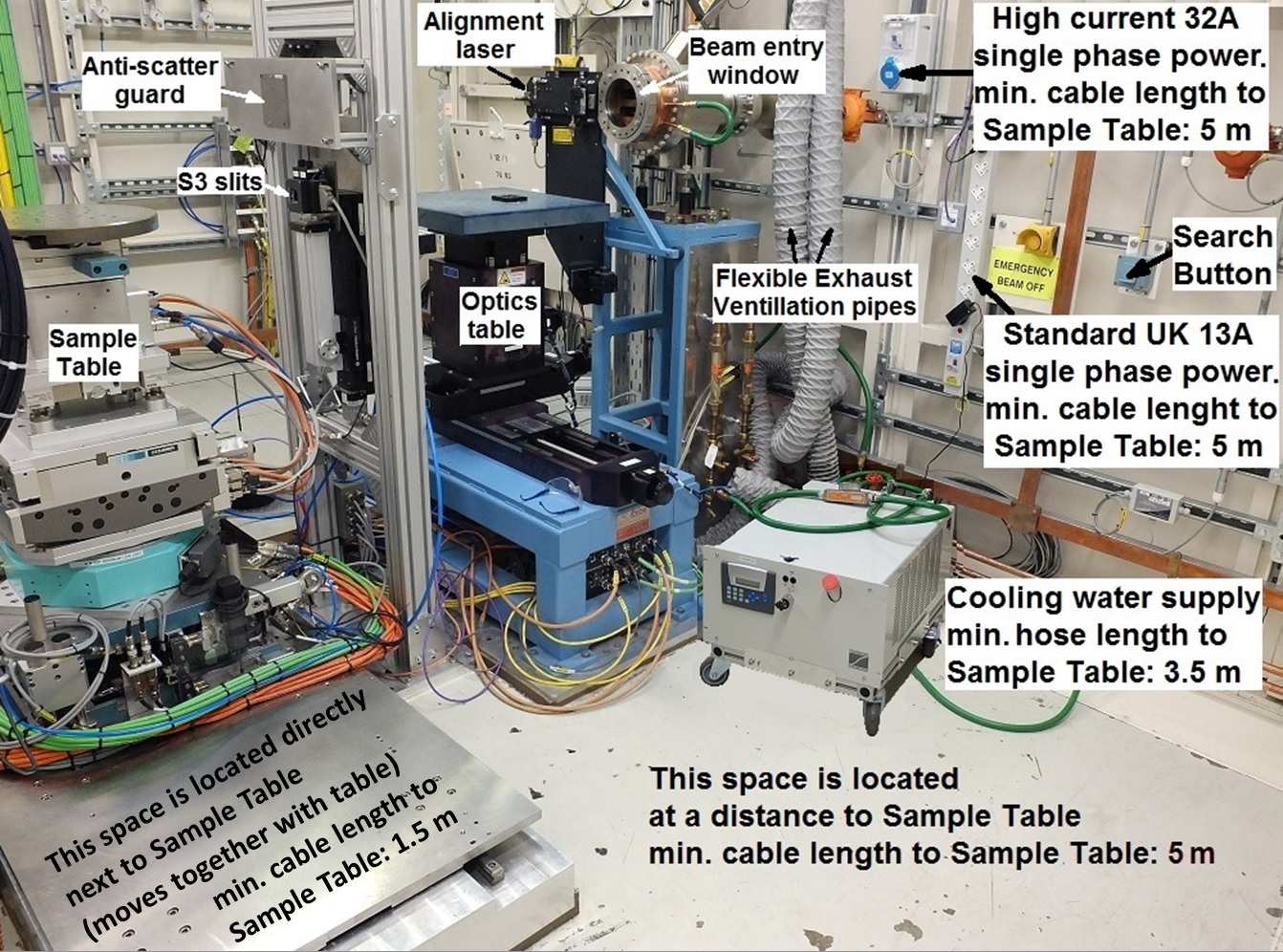
Additional space is available in close proximity to the Sample Table 1. Location of standard UK 13A single power socket, high current 32 A single power socket, and cooling water supply for user equipment (cooling water supply will be removed if users do not need it) is shown. Path to Search Button should remain free.
| Type of space | Specifications | To use this space, you need to provide |
| Space located directly next to the Sample Table 1. | Area available: 50 cm × 70 cm; moves together with sample table; limited radiation protection is avialable | Your equipment requires: - min. cable length to sample table: 1.5 m - maximum weight 200 kg |
| Space located at a distance to the Sample Table 1. | Area available: 80 cm (L) × 60 cm (W) × 100 cm (H); limited radiation protection is available | Your equipment requires: - min. cable length to sample table: 5 m |
| Additional space not covered by the above options | Available upon request | Please get in touch with your local contact |
Large Detector Table 1 (LDT1)
The EH1 Large Detector Table (LDT1) is designed to take different detectors at the same time, each placed on a separate table module. Each module can be moved into beam position by traversing the whole table along the x-direction across the beam. This arrangement allows various detectors to be used during one experiment. As an example, one can perform a tomography experiment with the imaging cameras to determine the sample structure and subsequently investigate the stress state with the 2D area diffraction detector.
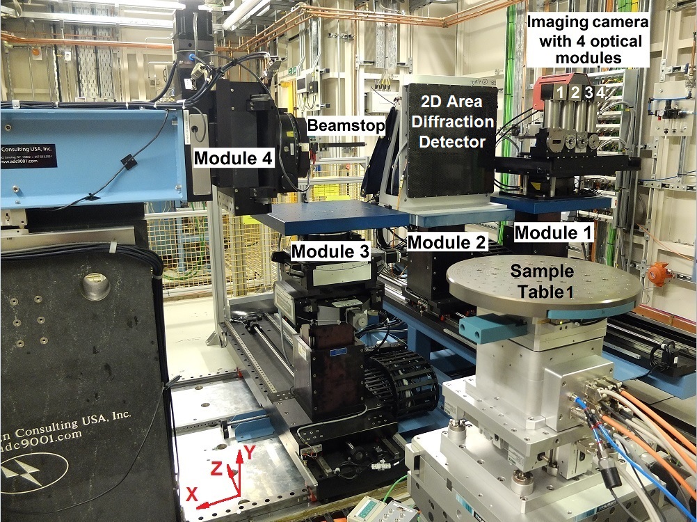
Large Detector Table 1 (LDT1) showing all 4 modules and various detectors: Module 1 with imaging camera, Module 2 with 2D Area Diffraction Detector, Module 3 (empty), Module 4 with Beamstop. Sample Table is shown in front of Large Detector Table 1. Coordinate system is shown for available movement of different modules of LDT 1 (see table below).
| Module | Available motions |
| Overall x-translation | · x-translation to switch between Modules 1, 2, and 3, as well as for horizontal alignment of detector on each module |
| Module 1 (imaging cameras) | · used for imaging cameras in standard configuration, but can be also used for any custom cameras and detectors · movement between different camera modules (x-translation) at fixed sample-to-camera distance using overall x-translation · y-translation (vertical): +/-50 mm · z-translation (changing sample-to-detector distance): from 550 to 2400 mm (allows positioning of the camera modules very close to the sample, e.g. for absorption contrast tomography) |
| Module 2 (2D area diffraction detector) | · used for 2D area diffraction detector in standard configuration, but can be also used for any custom cameras and detectors · movement 2D area diffraction detector at fixed sample-to-detector distance for centring beam at any point of detector (using horizontal overall x- translation and vertical y-translation) · y-translation (vertical): +/-50 mm · z-translation (changing sample-to-detector distance): from 550 to 2400 mm |
| Module 3 (custom equipment: cameras, detectors) | · for use with any detector (non-standard setting) · y-translation (vertical): +/-50 mm · rx-rotation: +/- 5o in step 0.01o · ry-rotation: +/- 90o in step 0.01o · rz-rotation: +/- 5o in step 0.01o · z-translation (changing sample-to-detector distance): from 750 to 2400 mm |
| Module 4 (beamstop or custom equipment) | · standard configuration: moving beamstop in and out of beam (i.e. for changing between diffraction and imaging mode · non-standard configuration: allows installation of custom optics, different small cameras and special detectors (including users’ custom cameras and detectors) instead of beamstop · up to 5 kg weight capacity · x-translation (horizontal): +/-175 mm · y-translation (vertical): +/-50 mm · rx-rotation: +/- 180o in step 0.01o · ry-rotation: +/- 5o in step 0.01o · z-translation (changing sample-to-detector distance): fixed at 55 mm (distance from the centre of rotation of sample table), needs custom-made arms to change distance. |
Small Detector Table 1 (SDT1)
The Small Detector Table 1 is located at the back of the EH1 at a distance 4500 mm from the sample table, and can be moved through the hutch perpendicular to the beam direction up to an angle of max. 15o (in respect to the incident beam and the sample position). This allows to carry out diffraction and wide angle scattering experiments with the 2D area diffraction detector. With the table at 0o it can be used for small-angle scattering for particles of size below 12 nm.
Small Detector Table 1 (LDT1) with installed 2D Area Diffraction Detector Pilatus and beamstop. Coordinate system is shown for available movement of different modules of SDT 1 (see table below).
| Equipment | Available motions |
| Small Detector Table |
· coarse x-translation perpensicular to beam direction: from 0 to 2200 mm (standard setting in beam position at 0 mm) · fine x-translation +/- 50 mm · y-translation +/- 100 mm |
Optics Table, Anti-Scatter Guard, and Anti-Scatter Slits (S3 slits)
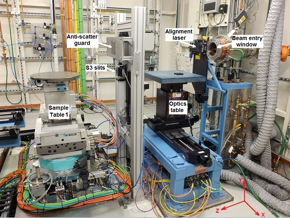
Optics table, anti-scatter guard, and anti-scatter S3 slits in EH1 in regards to Sample Table 1 with coordinate system.
The beam entry has two windows: for monochromatic beam (upper window) and for white beam (lower window). Switching between monochromatic and white beam takes ca. 30 min.
The alignment laser allows to approximate sample and detector alignment.
The Optics table can accommodate additional equipment, which can be moved into the beam. Available motions of optics table are: x-translation: +/-150 mm; y-translation: +/-50 mm; z-translation: +/-50 mm.
Remotely controlled anti-scatter S3 slits (with variable size and positon) can be used. The rectangular size of these slits can be varied in both directions from 0.05 mm to 10 mm (remote control of slits’ size is important for combined tomography/diffraction experiment).
Additional Equipment
1. Power supply / Electricity
2. Cooling water
3. Pressurised gases
4. Transportation and lifting equipment
5. User chicanes for cable access between Control Room and Experimental Hutch
6. Exhaust system
7. Signalling from and to beamline
1. Power supply / Electricity
| Type of electricity | Specifications | To connect to this equipment, you need to provide |
| Standard UK 13A single phase power | Multiple 13A 230V UK mains connections - socket: standard UK mains 13A | Your equipment requires: - min. cable length to sample table: 5 m - connector: standard UK mains 13A plug - portable Appliance Testing (PAT) of user equipment |
| High current 32A single phase power | One 32A 230V single phase power connection - socket: 32A 240V/230V 2P+E female IP44 IEC309 | Your equipment requires: - min cable length to sample table: 5 m - connector: 32A 240V/230V 2P+E male IP44 IEC 309 (blue) - portable Appliance Testing (PAT) of user equipment |
| High current 32A three phase power | Two 32A 400V three phase power connections | Your equipment requires: - min. cable length to sample table: 8 m - connector: 32A 380/415V 3P+N+E male IP44 IEC 309 (red) - high voltage test certificate or other evidence that the equipment has been safety tested |
2. Cooling water
Cooling water supply for user sample environment is available upon request. User equipment can be connected to a beamline heat exchanger. Ensure that your cooling circuit is clean!
| Type of cooler | Specifications | To connect to this equipment, you need to provide |
| Heat exchanger Thermal Exchange LR6U80-W-CC-5 | - process flow rate: 12 L/min - delivery pressure: 4 bar - process fluid temperature range: 25°C - 60°C | Your equipment requires: - max. cooling power: 8 kW - cooling water hose 3/8” inside diameter hose - pressure rating: min. 12 bar G - min. hose length to sample table: 3.5 m - connectors: (RS International stock 387-2555) & (RS International stock 387-2583) |
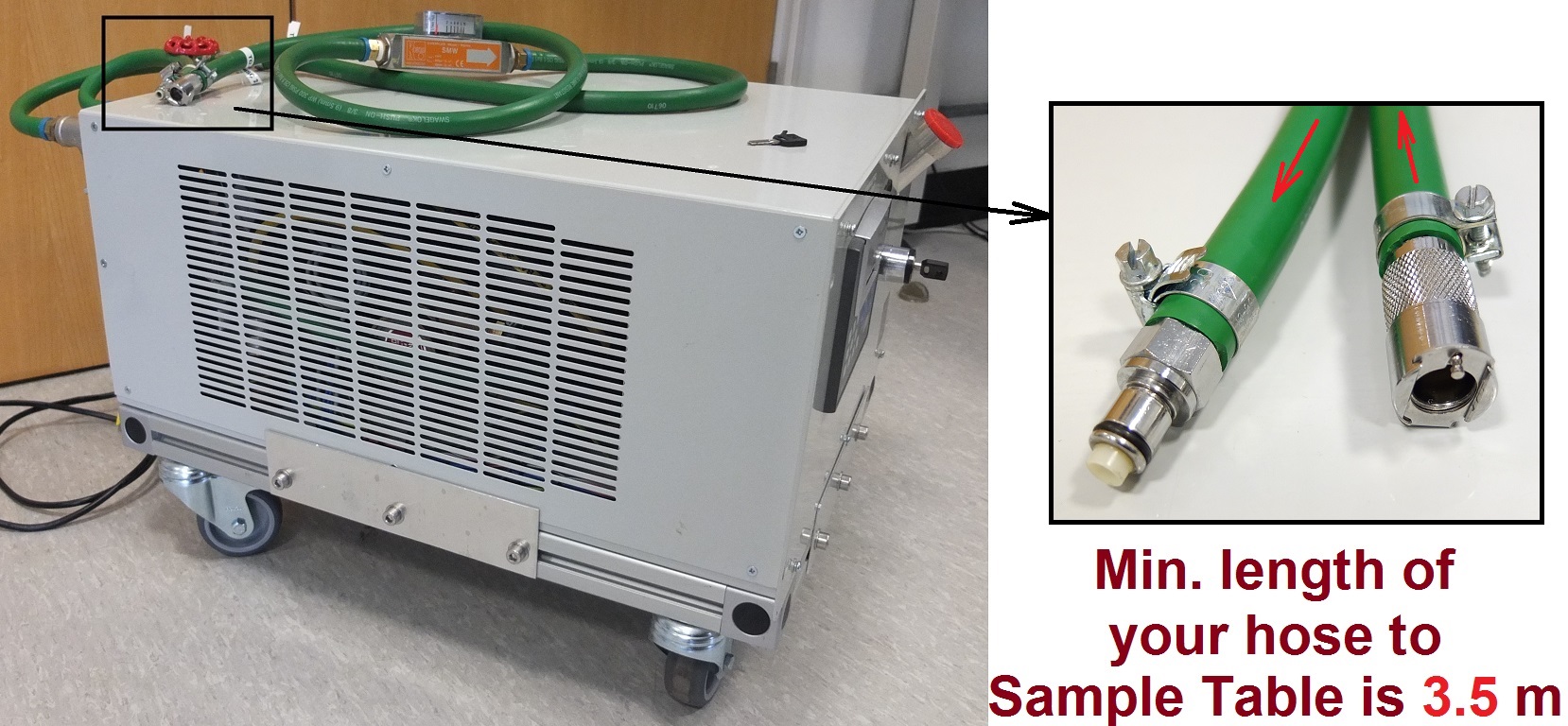
Cooling water supply. Left: cooler with tubes. Right: Detail picture of tube connections. The flow direction is indicated by red arrows. Your equipment should have suitable connectors as described in the table above.
3. Pressurised gases
| Type of gas | Specifications | To connect to this equipment, you need to provide |
| Pressurised gas supply (Ar, CO2, N2, He, air). All gases with purity BIP. | - pressure range max. 10 bar - connector: 6 mm or 8 mm push fit connector - delivery time: approx. 2-3 weeks | Your equipment requires: - air hose diameter: 6 mm or 8 mm - pressure rating: min. 15 bar G (for hose) - min. pipe length to sample table: 5 m - if equipment is operating under pressure, you MUST have a recent certificate that the equipment has been pressure tested |
| Special gases and gases with high purity. | - pressure range max. 10 bar - connector: 6 mm or 8 mm push fit connector - delivery time: 1-2 months depending on requested gas | Your equipment requires: - air hose diameter: 6 mm or 8 mm - pressure rating: min. 15 bar G (for hose) - min. pipe length to sample table: 5 m - if equipment is operating under pressure, you MUST have a recent certificate that the equipment has been pressure tested - if you require special gases, please contact I12 beamline team well in advance: special gases and gases with high purity can require 2 months of delivery |
4. Transportation and lifting equipment
Help with transportation of large equipment can be given by prior arrangement. All equipment should be delivered on a standard EUR-pallet.
Inside the Experimental Hutch, a crane can be used for lifting equipment. The beamline 1 tonne crane must only be operated by beamline staff.
| Equipment | Specifications | You need to provide |
| Pallet truck or Fork lift | By prior arrangement only. Cannot be used inside the Experimental Hutch. Please discuss with your Local Contact. | Your equipment needs to be brought in on EUR-pallet. |
| 1 tonne crane | By prior arrangement only. Used inside the Experimental Hutch. The crane must only be operated by beamline staff. | Appropriate lifting points or mounts for lifting eyes (sizes M8, M10, M12) attached to your equipment. |
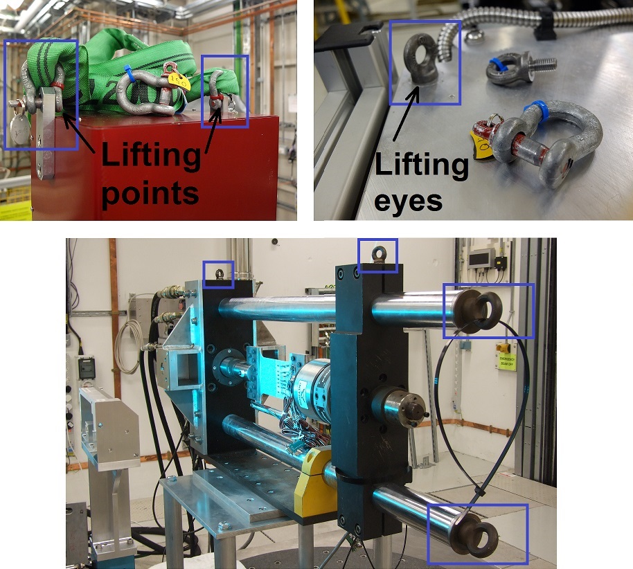 Examples of lifting points and lifting eyes, attached to equipment, which users must provide to make possible the lifting of their equipment with a beamline crane.
The “crane hook-to-floor” height is approx. 2600 mm.
Depending on the configuration of Sample Table 1 used in experiment, the maximal height of your equipment, which is possible to move on Sample Table 1 by crane, will be different.
For different configurations of Sample Table 1 (download here) and assuming 300 mm for rigging gear:
| Configuration No. of Sample Table 1 | Distance from the top of Sample Table 1 to hook (mm) | Max. equipment height (mm)* |
| 1 | 1290 | 990 |
| 2 | 1440 | 1140 |
| 3 | 1440 | 1140 |
| 4 | 1570 | 1270 |
| 5 | 1550 | 1250 |
| 6 | 1700 | 1400 |
| 7 | 1700 | 1400 |
| 8 | 1830 | 1530 |
* These values are for guidance only! They depend on the exact attachment of load and can be different. Please contact Beamline Staff if you have questions.
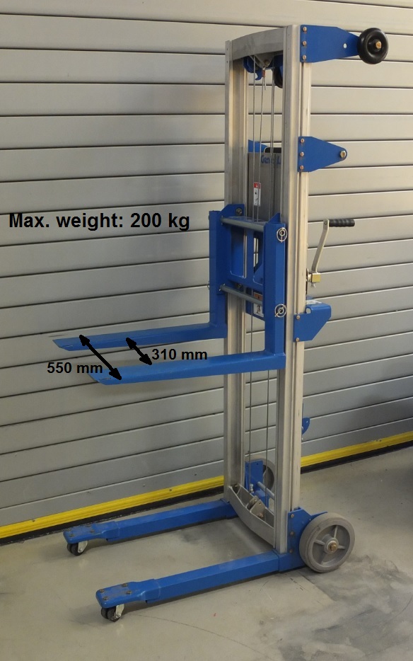
Trolley for lifting equipment out of users' car. Please, ensure the correct orientation of the pallet with your equipment in the car.
5. User chicanes for cable access between Control Room and Experimental Hutch
| Equipment | Specifications | To use equipment, your equipment requires |
| User chicane to Control Cabin | One user chicane is available in EH1 for direct routing of cables from the Experimental Hutch into the Control room. The chicane is frequently used to connect user equipment in the Experimental Hutch to user supplied PCs in the Control Room. This then allows operating the user equipment remotely without having entered the Experimental Hutch and interrupted experiment. | min. cable length 15 m |
| User chicane to CIA and corridor | One user chicane is available in EH1 for direct routing of cables from the Experimental Hutch into CIA (allows receiving/sending analogue and digital signals between beamline and user equipment) and to corridor. | min. cable length 10 m |
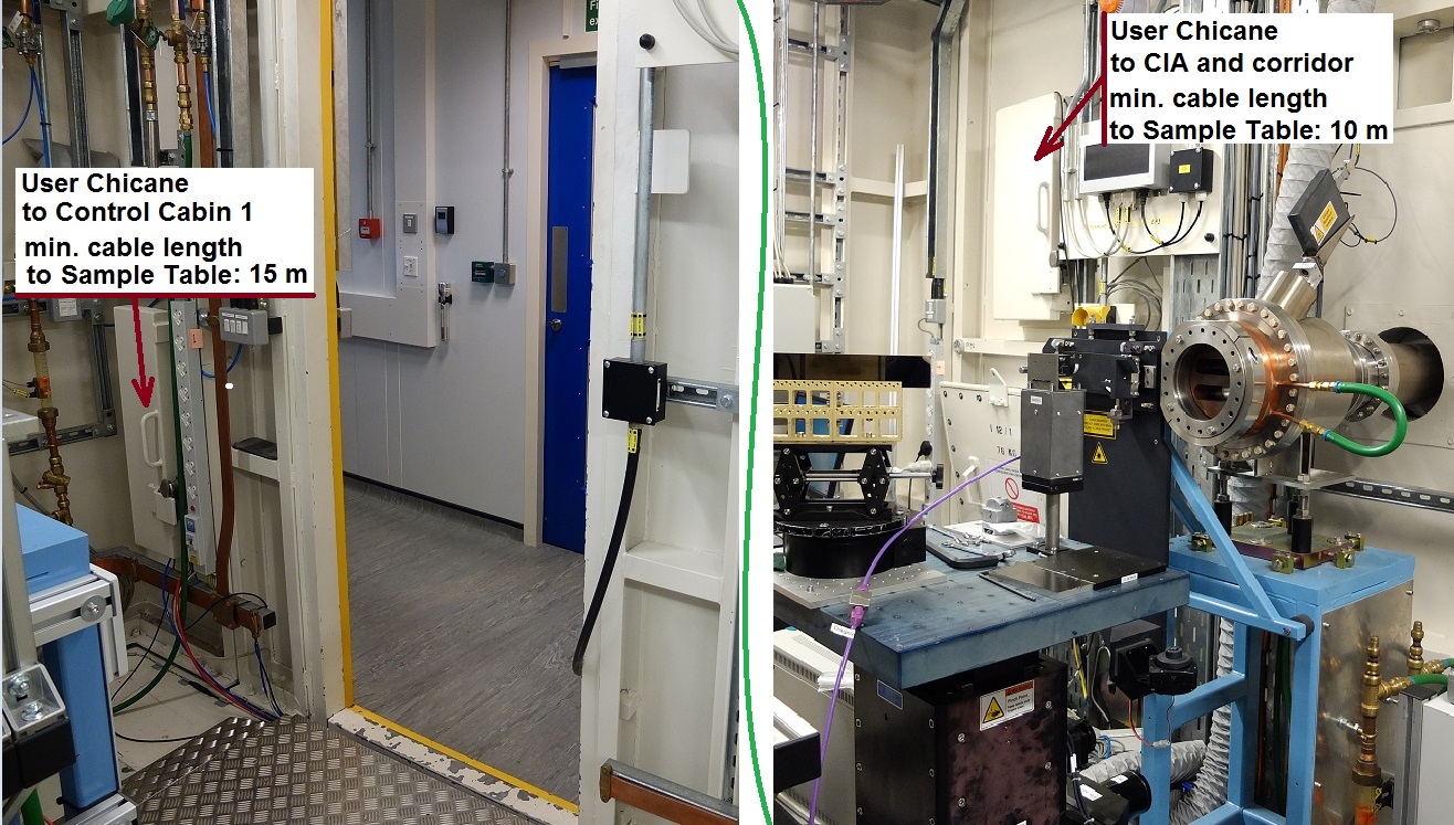
User chicanes from Experimental Hutch to Control Cabin 1 (on the left) and to CIA and corridor (on the right).
6. Exhaust system
Experimental Hutch 1 has installed an exhaust system with a maximal flow rate of 5.7 m/s = 44.7 l/s in a single 100 mm diameter duct. The exhaust system can be installed above or close to Sample Table 1. Please, contact your local contact or Beamline Staff if you need to use an exhaust system.
7. Signalling from and to beamline
| Type of connection | Specifications | To connect to this equipment, your equipment requires |
| Ethernet connection | - direct patch through from the Experimental Hutch 1 to the Control Cabin 1. - allows controlling of user equipment in the hutch with a user’s computer located in control room. Note: it is NOT permitted to connect user computers to the beamline network. | - Ethernet cables, computers with Remote Desktop software available or suitable software for closed networking between two computers. |
| Analogue beamline inputs | - to send signals from your equipment to the beamline. - 3 analogue inputs from -10 to +10 V. 16-bit resolution with a default sample rate of 1 kHz - Two readouts:(a) Average over 100 samples (single value), (b) Sliding 10 second buffered (as a waveform). - connectors: BNC type | - connector: BNC type to send signals from your equipment to the beamline. - min. cable length: 10 m - please get in touch with your Local Contact. |
| Digital beamline outputs | - to receive signals from the beamline to your equipment. - 3 low voltage TTL outputs (3.3 V) @ 100 mA. - connectors: BNC type. | - connector: BNC type to receive signals from the beamline to your equipment. - min. cable length: 10 m - please get in touch with your Local Contact. |
| Thermocouple inputs | - temperature readout of K-type thermocouples using the beamline control system. - 6 sockets with K-type female “mini” sockets are available close to Sample Table 1 | - K-type thermocouples with male K-type “mini” plug. - extension/compensation cable with min. length: 2 m |

Diamond Light Source is the UK's national synchrotron science facility, located at the Harwell Science and Innovation Campus in Oxfordshire.
Diamond Light Source Ltd
Diamond House
Harwell Science & Innovation Campus
Didcot
Oxfordshire
OX11 0DE
Copyright © Diamond Light Source. Diamond Light Source® and the Diamond logo are registered trademarks of Diamond Light Source Ltd
Registered in England and Wales at Diamond House, Harwell Science and Innovation Campus, Didcot, Oxfordshire, OX11 0DE, United Kingdom. Company number: 4375679. VAT number: 287 461 957. Economic Operators Registration and Identification (EORI) number: GB287461957003.