Instruments by Science Group
I12 Contact
Science Group Leader
Julia Parker
Email: [email protected]
Tel: +44 (0)1235 778924
I12 JEEP: Joint Engineering, Environment and Processing
Status: Operational
Beamsize: From 50 micrometer x 50 micrometer to 50 mm x 15 mm (EH1) or 100 mm x 30 mm (EH2)
Energy: 53 – 150 keV
Energy: 53 – 150 keV
| Distance from sample to source: | 95 m |
| Maximum beam size: | ~ 95 mm horizontally and ~ 30 mm vertically |
| Hutch dimensions: | 11 m long × 7 m wide × 4 m high (clear) |
| Sample Table: | Combined tomography and diffraction sample table |
| Sample Table capacity: | Up to 2000 kg for heavy engineering components. Scannable area 1 m (H) × 1 m (V) with full rotation. |
| Overhead crane capacity: | 5000 kg |
Experimental Hutch 2 (EH2) layout
· EH2 Large Sample Table (for samples and sample environments)
· EH2 Large Detector Table with three modules (for detectors, imaging cameras, and additional equipment)
· EH2 Small Detector Table (for detectors and imaging cameras)
· EH2 Optics Table (for additional instruments to go before sample)
· EH2 Additional Equipment (power, cooling water, pressurised gases, manual crane, user chicanes, signalling from and to beamline)
· INSTRON 100 kN uniaxial mechanical test rig for in situ diffraction and imaging experiments (when installed on Large Sample Table) and for ex situ sample preparation or offline use.
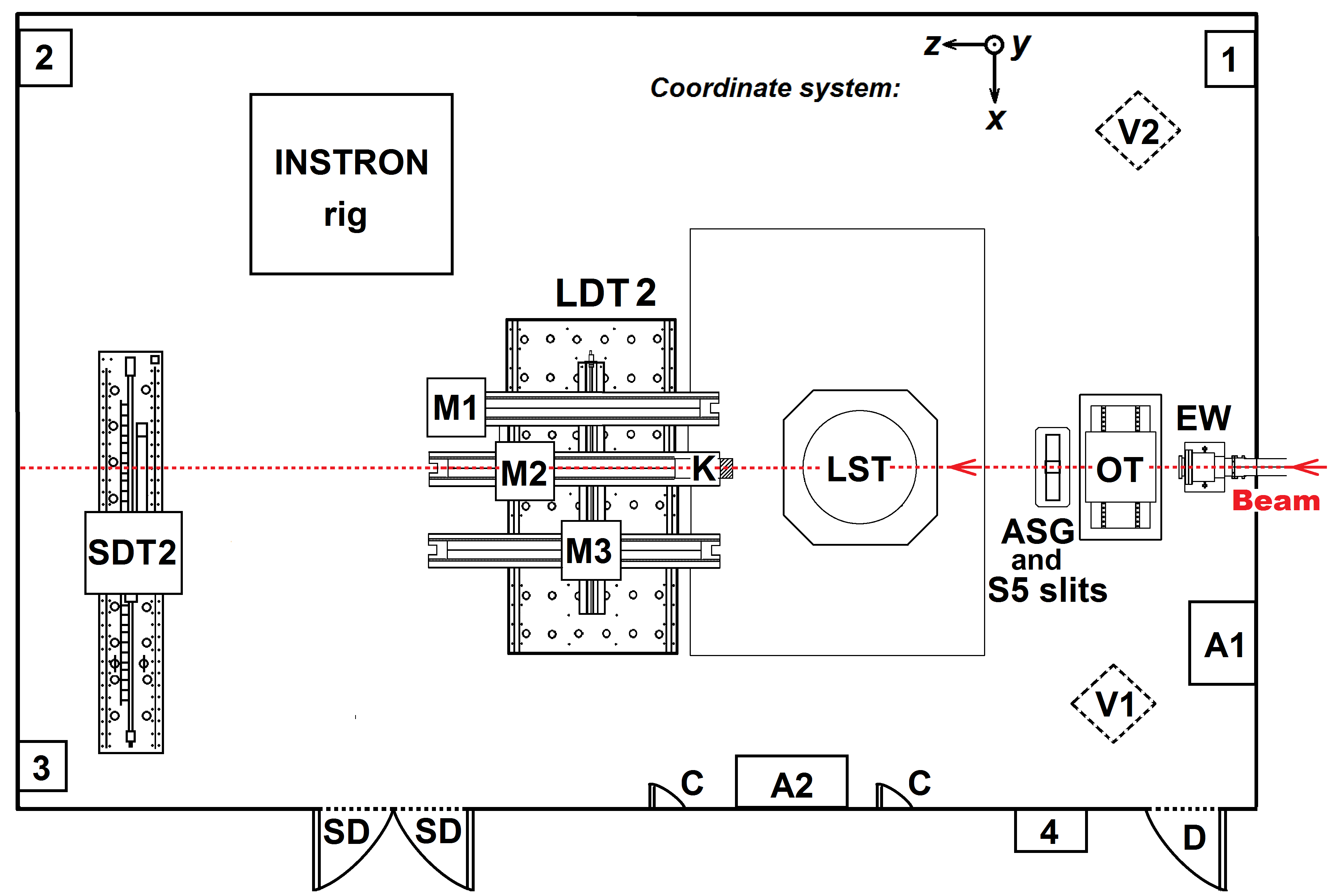
Schematic of Experimental Hutch 2 (EH2).
- Red dashed line – X-ray beam direction.
- Numbers 1, 2, 3, 4 – series of interlocks, which should be activated in a predefined sequence during search procedure for taking beam into EH2
- EW – beam Entry Window
- OT – Optical Table.
- ASG and S5 slits – Anti-Scatter Guard and remotely controlled clean-up S5 slits for imaging and diffraction.
- LST – Large Sample Table.
- LDT2 – Large Detector Table with three modules M1, M2, and M3. M1 – module 1 for Large Field of View camera assembly (installation of 2D Area Diffraction detector which is off-centered relative to the beam is possible in front of Large Field of View camera assembly); M2 – module 2 for energy-dispersive detector; M3 – module 3 for custom detectors and cameras, or for 2D Area Diffraction detector, or for imaging camera modules; K – submodule of module 2 for EDXD collimator, small imaging camera, or special instruments.
- SDT2 – Small Detector table
- A1 – high-current single phase and high-current three phase power supply.
- A2 – standard single phase power supply and Ethernet connections.
- C – user chicane from EH2 to corridor.
- D – door from EH2 to corridor.
- SD – service doors from EH2 to corridor.
- V1 – first point of downstream view of EH2 (image below).
- V2 – second point of downstream view of EH2 (image below).
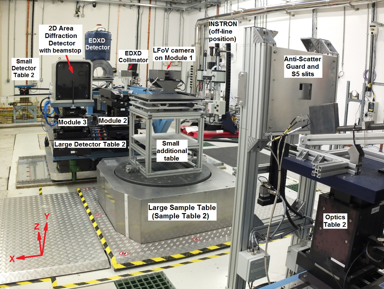
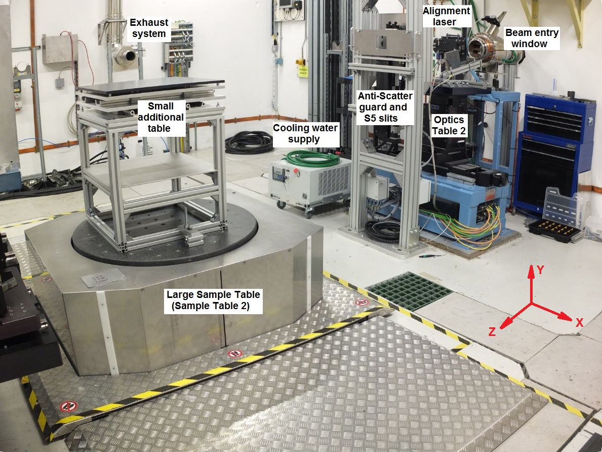
Downstream view of EH2 (first view point V1 on EH2 schematic above), with xyz-coordinate system (z-axis is along the beam, y-axis is vertical, x-axis is horizontal perpendicular to beam). Optics table; Anti-Scatter Guard and S5 slits; Large Sample Table; Large Detector Table with remotely controlled Module 1 (with Large Field of View camera), Module 2 (dedicated for EDXD Detector), Module 3 (with 2D Area Diffraction detector in place, other detectors can be placed here) ; Small Detector Table (empty, can be used with other detectors. Mostly used with small X-ray camera to assist sample alignment).
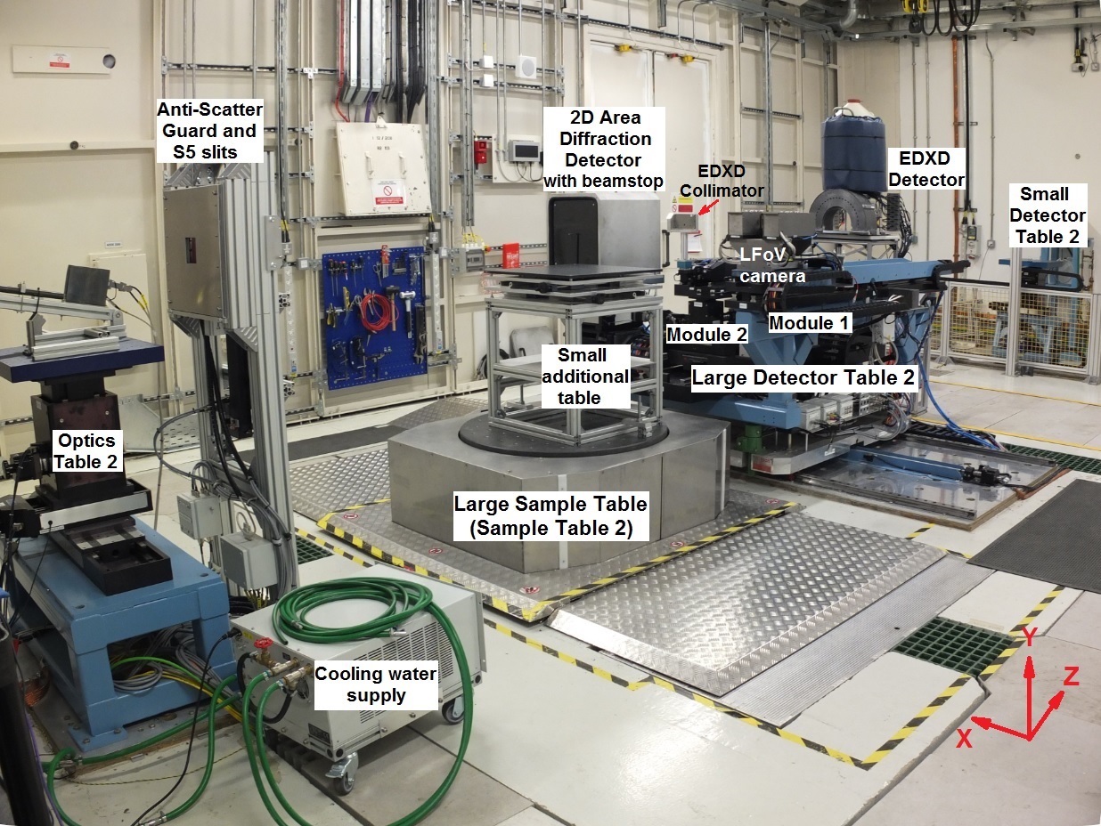
Downstream view of EH2 (second view point V2 on EH2 schematic above), with xyz-coordinate system (z-axis is along the beam, y-axis is vertical, x-axis is horizontal perpendicular to beam). Optics table; Anti-scatter Guard and S5 slits; Large Sample Table; Large Detector Table with remotely controlled Module 1 (with Large Field of View camera), Module 2 (dedicated for EDXD Detector), Module 3 (with 2D Area Diffraction detector, other detectors can be placed here for custom setups), Small Detector Table (empty, usually used with small X-ray imaging camera to assist sample alignment).
More detailed drawings of EH2 (incl. CAD models) are available upon request from the I12 beamline staff.
Sample Table 2 (ST2)
1. Technical description of Sample Table 2
Sample table 2 is designed to take heavy loads of up to 2000 kg in weight. This table is in a pit in the hutch floor.
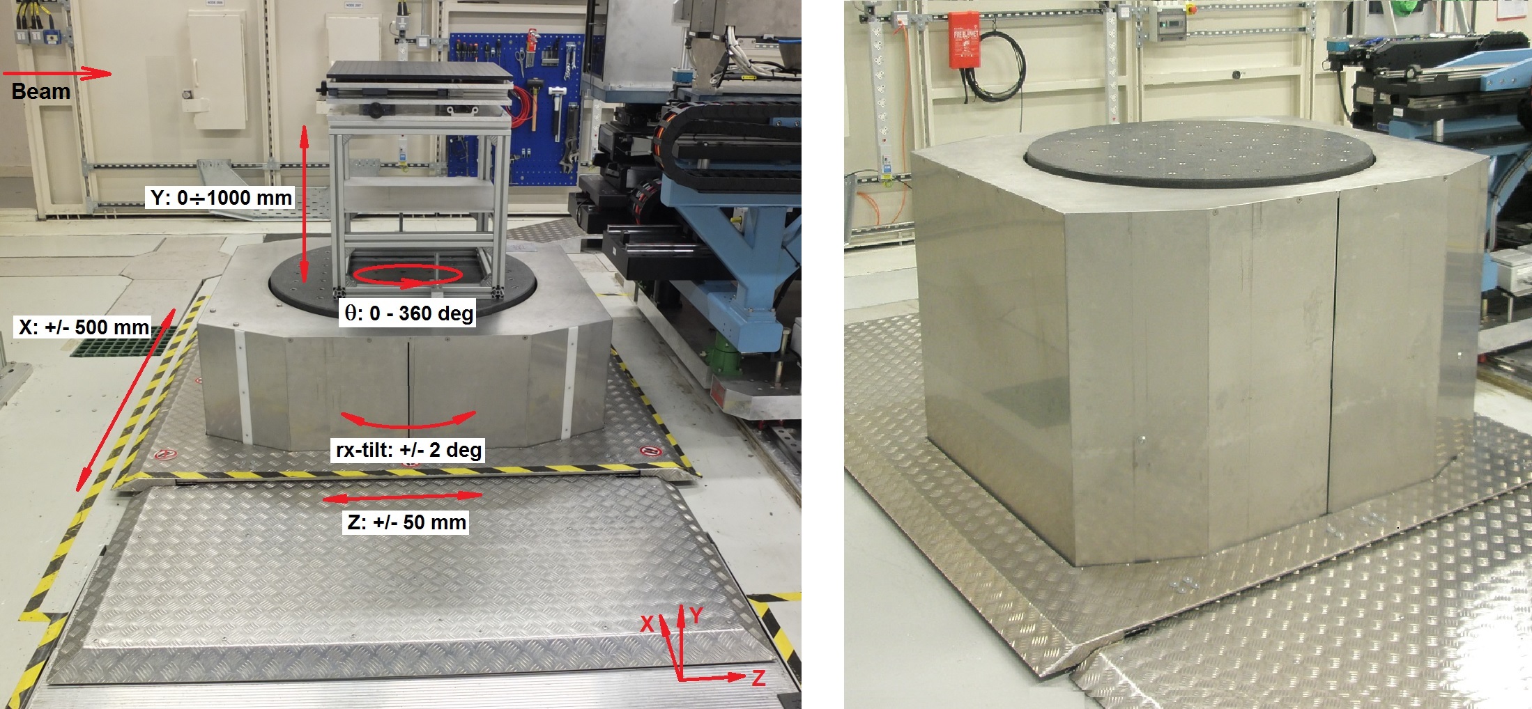
Large Sample Table (ST2) in Experimental Hutch 2 with all available motions and with small additional table on it (left); Large Sample Table (ST2) without additional table at maximum Y translataion 1000 mm (right).
| Available motions | Range of motions |
| x-movement for scanning through the sample |
|
| z-movement for scanning through the sample |
|
| y-movement for scanning sample through beam and switching between white beam and monochromatic beam |
|
| Alignment of virtual rotation axis for tomography |
|
| Continuous sample rotation around y-axis for tomography and diffraction experiments |
|
2. Experimental arrangement of Sample Table 2
Please, consider making a support plate for your equipment compatible with the I12 Sample Table interface to avoid mounting problems during installation of your equipment. More details about the available sample table configurations are available here.
- If equipment is mounted directly on the Sample Table 2 (configuration 1 on the scheme below), please use the drawing of Sample Table 2 interface plate.
- If small or large additional tables are used (configuration 2 and 3 on the scheme below), please use the drawing of interface plate.
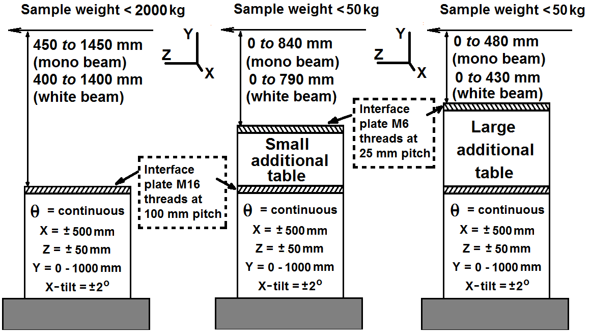
Possible configurations of Sample Table in EH2 with distances (in mm) from the top interface plate to the white and monochromatic beams. Your sample needs to have a height between the indicated values for exposing by X-rays. Important: for EDXD measurements available distance from top interface plate to beam is limited – please contact beamline staff for clarification if you plan to perform EDXD measurements.
Additional space is available in close proximity to the Sample Table 2. This space is allocated for the positioning of user equipment that needs connection to the sample environment, e.g. rig controllers, computers etc.
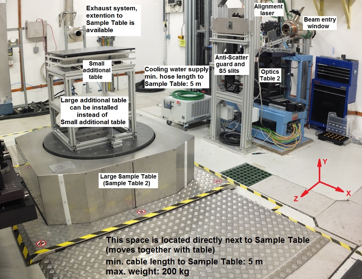
Additional space is available in close proximity to the Sample Table 2. Location of standard UK 13A single power socket, high current 32 A single power socket, and cooling water supply for user equipment (cooling water supply will be removed if users do not need it) is shown.
| Type of space | Specifications | To use this space, you need to provide |
| Space located directly next to the Sample Table 2. | Area available: 200 cm × 100 cm; moves together with the table; limited radiation protection is availble | Your equipment requires: |
| Space located at a distance to Sample Table 2. | Area available: 200 cm (L) × 100 cm (W) | Your equipment requires: |
| Additional space not covered by the above options. | Available upon request | Please get in touch with your local contact |
Large Detector Table 2 (LDT2)
The EH2 Large Detector Table (LDT2) is designed to take different detectors at the same time, each placed on a separate table module. Each module can be moved into beam position by translating the whole table along the x-direction (i.e. across the beam). This arrangement allows various detectors to be used during one experiment.
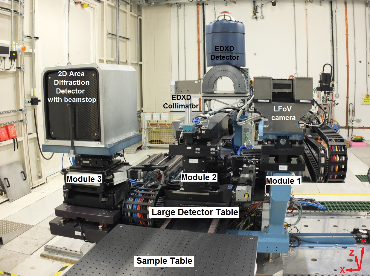
Large Detector Table in EH2 (LDT2) with Large Field of View (LFoV) camera assembly on Module 1; EDXD detector on Module 2 and EDXD collimator on submodule of Module 2; 2D Area Diffraction detector Pilatus (moved from EH1) with beamstop mounted in front of it on Module 3. Instead of EDXD collimator a small imaging camera or beamstop can be mounted on Module 2. Module 3 can be used for custom detector setups, or for imaging camera modules (can be moved from EH1). xyz-coordinate system is shown (z-axis is along the beam, y-axis is vertical, x-axis is horizontal perpendicular to beam).
| Module | Available motions |
| Overall x-translation |
· x-translation: +/- 1000 mm to switch between Modules 1, 2, and 3, as well as for horizontal alignment of detector on each module |
| Overall y-translation |
· y-translation: +/- 50 mm to adjust height on all modules 1, 2, and 3 simultaneously |
|
Module 1 (Large Field of View camera) |
· used for Large Field of View camera in standard configuration, but can also be used for any custom cameras and detectors or for 2D Area Diffraction detector · z-translation (manual changing of sample-to-detector distance): from 1000 to 2200 mm |
|
Module 2 (EDXD detector) |
· used for EDXD detector in standard configuration · includes additional unit for mounting collimator when EDXD detector is used. Alternatively, small cameras can be mounted (only if EDXD is not used for experiment) with available z-translation: from 1000 mm to 1500 mm |
|
Module 3 (custom equipment: cameras, detectors) |
· allows installation of custom optics, different cameras and special detectors (including users’ custom cameras and detectors) · rx-rotation: +/- 5o in step 0.01o · ry-rotation: +/- 90o in step 0.01o · rz-rotation: +/- 5o in step 0.01o · z-translation (changing sample-to-detector distance): from 1000 to 2600 mm |
Small Detector Table 2 (SDT2)
The Small Detector Table 2 is located at the back of the EH2 at a distance 6300 mm from the sample table, and can be moved through the hutch perpendicular to the beam direction up to an angle of max. 15o from the incident beam direction. This allows to carry out the diffraction and wide angle scattering experiments with the 2D area diffraction detector. With the table at 0o it can be used for small-angle scattering studies of particles smaller than 16 nm.
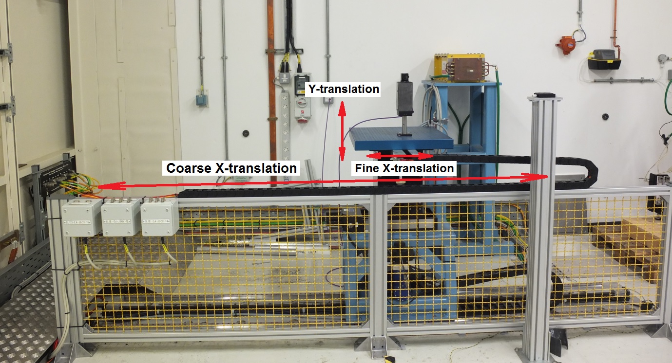
Small Detector Table in EH2 (SDT2) with diagnostic camera installed.
| Equipment | Available motions |
| Small Detector Table |
· coarse x-translation perpensicular to beam direction: from 0 to 2200 mm (standard setting in beam position at 0 mm) · fine x-translation +/- 50 mm · y-translation +/- 100 mm |
Optics Table, Anti-Scatter Guard, and Anti-Scatter slits (S5 slits)
Optics table, anti-scatter guard, and anti-scatter S5 slits in EH2 in regards to Sample Table 2 with coordinate system.
The beam entry has two windows: one for monochromatic beam (upper window) and one for white beam (lower window). Switching between monochromatic and white beam takes ca. 30 min.
The alignment laser allows approximate sample and detector alignment.
The Optics table can accommodate additional equipment, which can be moved into the beam. Available motions of optics table are: x-translation: +/-150 mm; y-translation: +/-50 mm; z-translation: +/-50 mm.
Different anti-scatter guards can be installed manually during experiment to decrease the air scattering.
Remotely controlled anti-scatter S5 slits (with variable size and position) can be used. The rectangular size of these slits can be varied in both directions from 0.05 mm to 15 mm (remote control of slits’ size is important for combined tomography/diffraction experiment).
EH2 Additional Equipment
- Power supply / Electricity
- Cooling water
- Pressurised gases
- Transportation and lifting equipment
- User chicanes for cable access between control room and hutch
- Exhaust system
- Signalling from and to beamline
1. Power supply / Electricity
| Type of electricity | Specifications | To connect to this equipment, you need to provide |
| Standard UK 13A single phase power | Multiple 13A 230V UK mains connections - connector: standard UK mains 13A plug |
Your equipment requires: - min. cable length to sample table: 7 m - connector: standard UK mains 13A plug - portable Appliance Testing (PAT) of user equipment |
| High current 32A single phase power | One 32A 230V single phase power connection - socket: 32A 240V/230V 2P+E female IP44 IEC309 |
Your equipment requires: - min cable length to sample table: 6 m - connector: 32A 240V/230V 2P+E male IP44 IEC309 (blue) - portable Appliance Testing (PAT) of user equipment |
| High current 32A three phase power |
Two 32A 400V three phase power connections One 63A 400V three phase power connection |
Your equipment requires: - min. cable length to sample table: 8 m - connector: 32A 380/415V 3P+N+E male IP44 IEC309 (red) - or connector: 64A 380/415V 3P+N+E male IP44 IEC309 - high voltage test certificate or other evidence that the equipment has been safety tested |
2. Cooling water
Cooling water supply for user sample environment is available upon request. User equipment can be connected to a beamline heat exchanger. Ensure that your cooling circuit is clean!
| Type of cooler | Specifications | To connect to this equipment, you need to provide |
| Heat exchanger Thermal Exchange LR6U80-W-CC-5 | Max. pressure 7 bar G process flow rate: 12 L/min delivery pressure: 4 bar process temperature range: 25°C - 60°C |
Your equipment requires: - cooling water hose 3/8” inside diameter hose - pressure rating: min. 12 bar G - min. hose length to sample table: 3.5 m - connectors: (RS International stock 387-2555) & (RS International stock 387-2583) |
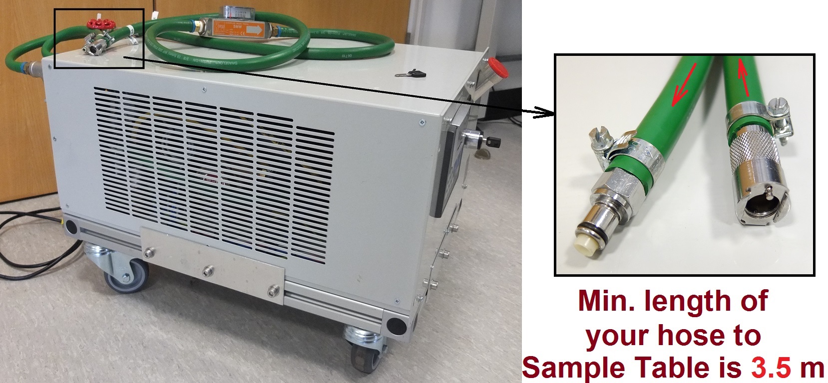
Cooling water supply (on the left). Your equipment should have suitable connectors (on the right) and minimal length of your hose from cooling water supply to Large Sample Table 2 should be 3.5 m.
3. Pressurised gases
| Type of gas | Specifications | To connect to this equipment, you need to provide |
|
Pressurised gas supply (Ar, CO2, N2, He, air). All gases with purity BIP. |
- pressure range max. 10 bar - connector: 6 mm or 8 mm push fit connector - delivery time: approx. 2-3 weeks |
Your equipment requires: - air hose diameter: 6 mm or 8 mm - pressure rating: min. 15 bar G (for hose) - min. pipe length to sample table: 5 m - if equipment is operating under pressure, you MUST have a recent certificate that the equipment has been pressure tested |
| Special gases and gases with high purity. |
- pressure range max. 10 bar - connector: 6 mm or 8 mm push fit connector - delivery time: 1-2 months depending on requested gas |
Your equipment requires: - air hose diameter: 6 mm or 8 mm - pressure rating: min. 15 bar G (for hose) - min. pipe length to sample table: 5 m - if equipment is operating under pressure, you MUST have a recent certificate that the equipment has been pressure tested - if you require special gases, please contact I12 beamline team well in advance: special gases and gases with high purity can require 2 months of delivery |
4. Transportation and lifting equipment
Help with transportation of large equipment can be given by prior arrangement. All equipment should be delivered on a standard EUR-pallet.
Inside the Experimental Hutch, a crane can be used for lifting equipment. The beamline electric crane with a lifting capacity of up to 5 tonnes must only be operated by beamline staff. For lifting of complex shapes, prior arrangements with the lifting crew are required. Please contact a member of the I12 beamline team to discuss your requirements.
| Equipment | Specifications | To use this space, you need to provide |
| Pallet truck or Fork lift |
By prior arrangement only. Cannot be used inside the Experimental Hutch. Please discuss with your Local Contact. |
Your equipment needs to be brought in on EUR-pallet. |
| 5 tonnes crane |
By prior arrangement only. Used inside the Experimental Hutch. The crane must only be operated by beamline staff. |
Appropriate lifting points or mounts for lifting eyes (sizes M8, M10, M12) attached to your equipment. |
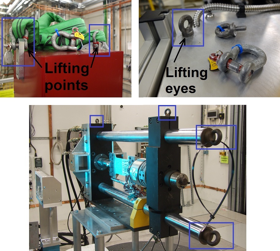 Examples of lifting points and lifting eyes, attached to equipment, which users should provide to make possible the movement of their equipment with a beamline crane.
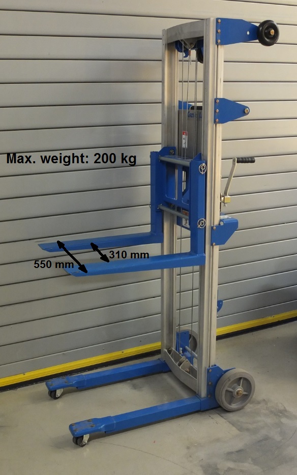
Trolley for lifting equipment out of users' car. Please, ensure the correct orientation of the pallet with your equipment in the car.
5. User chicanes for cable access between corridor and Experimental Hutch
| Equipment | Specifications | To use equipment, your equipment requires |
| User chicane to corridor |
Two user chicanes are available in EH2 for direct routing of cables from the Experimental Hutch to corridor.The chicanes are frequently used to connect user equipment in the Experimental Hutch 2 to user supplied PCs in the corridor. This allows operating the user equipment remotely without entering the Experimental Hutch 2 and interrupting experiment. |
min. cable length 10 m |
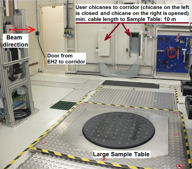
User chicanes from Experimental Hutch 2 to the corridor.
6. Exhaust system
Experimental hutch 2 has installed exhaust system with a maximal flow rate of 18.3 m/s = 144 l/s in a single 100 mm diameter duct. The exhaust system can be installed above or close to Sample Table 2. Please, contact your local contact or Beamline Staff if you need to use an exhaust system.
7. Signalling from and to beamline
| Type of connection | Specifications | To connect to this equipment, your equipment requires |
| Ethernet connection |
- direct patch through from the Experimental Hutch 2 to the Control Cabin 2. - allows controlling of user equipment in the hutch with a user’s computer located in control room. Note: it is NOT permitted to connect user computers to the beamline network. |
- Ethernet cables, computers with Remote Desktop software available or suitable software for closed networking between two computers. |
| Analogue beamline inputs | - to send signals from your equipment to the beamline. - 8 analogue inputs from -10 to +10 V. 16-bit resolution with a default sample rate of 1 kHz - Two readouts: (a) Average over 100 samples (single value), (b) Sliding 10 second buffered (as a waveform). - connectors: BNC type |
- connector: BNC type to send signals from your equipment to the beamline. - min. cable length: 30 m - please get in touch with your Local Contact. |
| Digital beamline outputs | - to receive signals from the beamline to your equipment. - 8 low voltage TTL outputs (3.3 V) @ 100 mA. - connectors: BNC type. |
- connector: BNC type to receive signals from the beamline to your equipment. - min. cable length: 30 m - please get in touch with your Local Contact. |
| Thermocouple inputs |
- temperature readout of K-type thermocouples using the beamline control system. - 5 sockets with K-type female “mini” sockets are available close to Sample Table 2 |
- K-type thermocouples with male K-type “mini” plug. - extension/compensation cable with min. length: 2 m |

Diamond Light Source is the UK's national synchrotron science facility, located at the Harwell Science and Innovation Campus in Oxfordshire.
Diamond Light Source Ltd
Diamond House
Harwell Science & Innovation Campus
Didcot
Oxfordshire
OX11 0DE
Copyright © Diamond Light Source. Diamond Light Source® and the Diamond logo are registered trademarks of Diamond Light Source Ltd
Registered in England and Wales at Diamond House, Harwell Science and Innovation Campus, Didcot, Oxfordshire, OX11 0DE, United Kingdom. Company number: 4375679. VAT number: 287 461 957. Economic Operators Registration and Identification (EORI) number: GB287461957003.