Instruments by Science Group
I16 Contact
Beamline Phone Number:
+44 (0) 1235 778616
Principal Beamline Scientist:
Alessandro Bombardi
Tel: +44 (0) 1235 778226
E-mail: [email protected]
I16 Materials and Magnetism
Status: Operational
Energy: 2.7 - 15 keV
Imaging
Spectroscopy
X-ray Diffraction
WAXS: Wide Angle X-ray Scattering
X-ray Single Crystal Diffraction
High Pressure
Scattering
Bragg CDI
CDI: Coherent Diffraction Imaging
Ptychography
GIWAXS: Grazing Incidence WAXS
SXRD: Surface X-ray Diffraction
Spectroscopy
XMLD: X-Ray Magnetic Linear Dichroism
XMCD: X-ray Magnetic Circular Dichroism
XRR: X-ray Reflectivity
REXS: Resonant Elastic X-ray Scattering
- Monochromator
- Phase Plates
- Mirrors
- Attenuators
- Harmonic Rejection
- Diffractometer
- Polarisation Analyser
- Pilatus3 100K
- QuadMerlin Detector
- Pilatus 2M
Channel-cut Si111 Monochromator
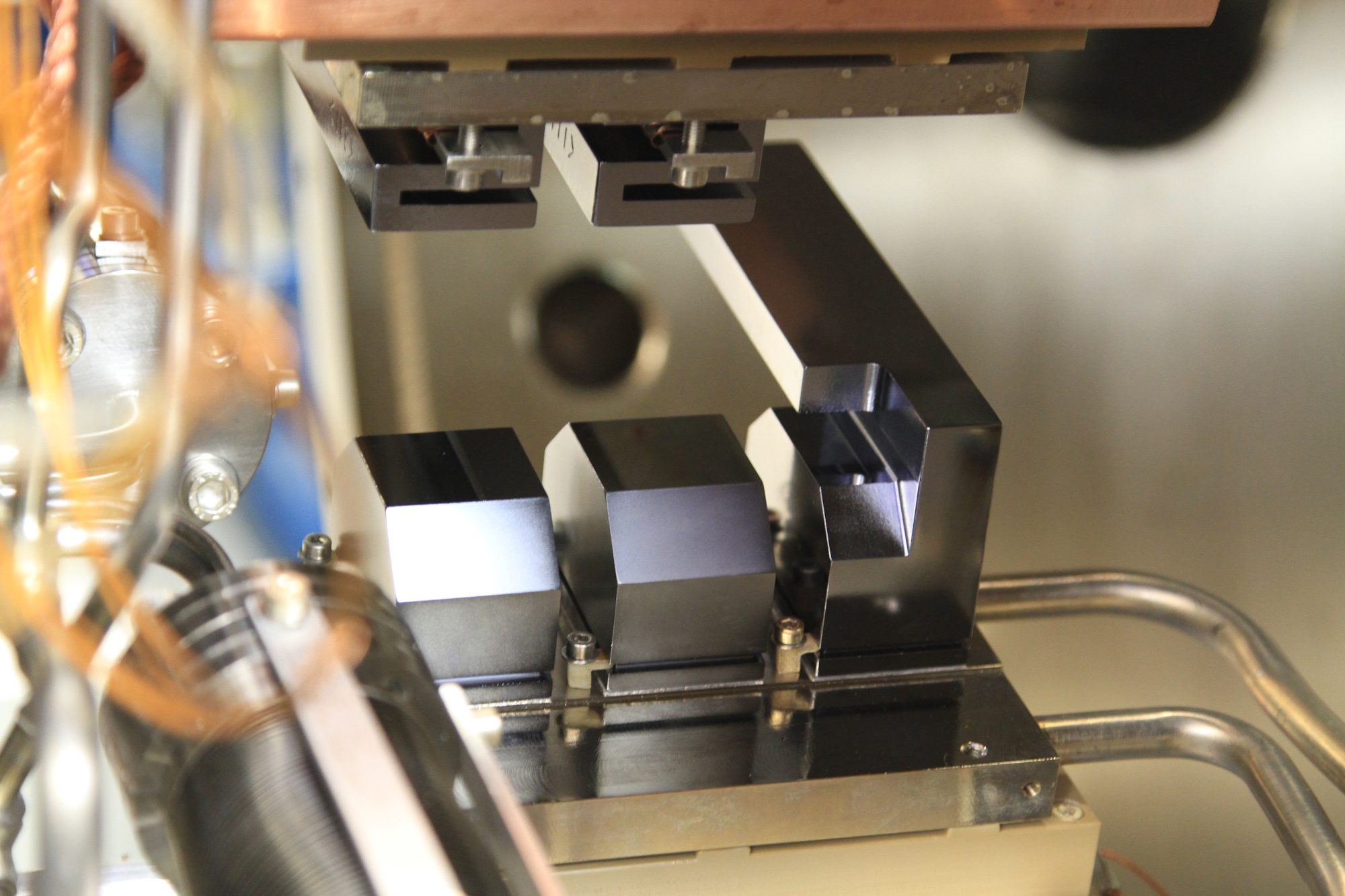
- I16 Si 111 channel cut monochromator
I16 uses a Si (111) monochromator providing an energy range between 3 and ~20 keV and an energy resolution of ΔE/E = 10-4.
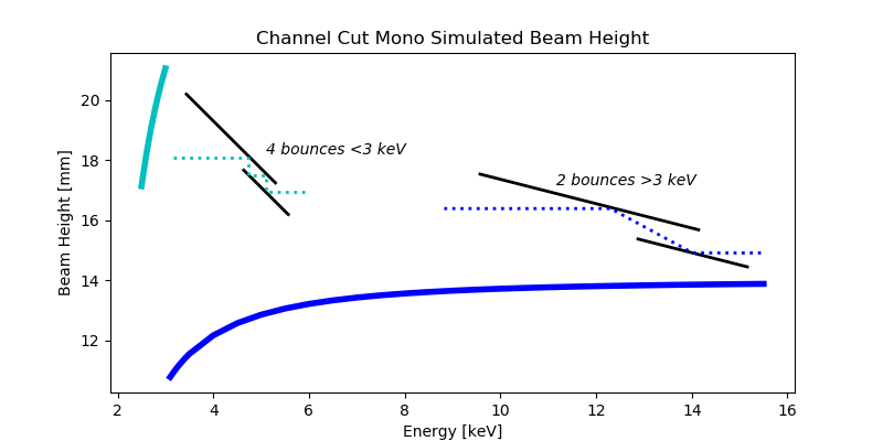
The channel cut monochromator gives I16 high flux and high stability, as well as the ability to change energy quickly without significant realignment. The fixed nature of the second reflection means that the beam height moves with energy, as all the beamline change height accordingly.
By performing a double-bounce on the monochromator it is possible to access lower energies below 3 keV.
Multi-Crystal Quarter-Wave Phase Retarder
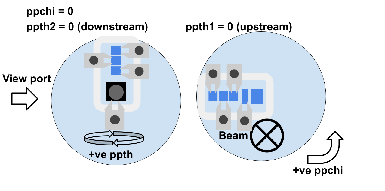
- Location and relative orientation of the phase plate crystals
I16 is equipped with a complex in-vacuum quarter-wave phase retarder to vary the incident polarization of the light from the linear horizontal provided from the insertion device to circular left or right from 2.8 to 10 keV and, linear with arbitrary orientation from zero (// to the synchrotron orbit) to 90 (perpendicular to the synchrotron orbit) from 3.5 to 9 keV.
Read more here: Polarisation Control and Analysis
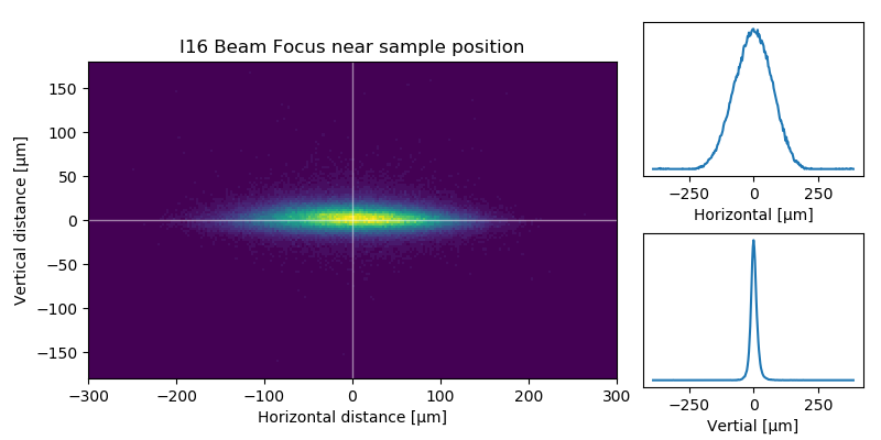
Horizontally Deflecting Focus Mirrors
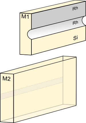
The main mirrors are used to focus the beam at the sample position to ~200 microns horizontally and 30 microns vertically. The mirrors sit at the 2:3 position, giving low beam divergence. Both mirrors are horizontally deflecting.
The first (vertically focusing) mirror is a 96mm sagittal cylinder, meaning the pitch controls the posiiton of vertical focus.
The second (horizontally focusing) mirror has a polished silicon strip and a Rh coated strip. Rh gives high reflectivity to the highest photon energies (~15 keV at the usual incidence angle of 4 mrad), whereas the si strip gives high reflectivity (very slightly higher than Rh) up to 8 keV, and is used to provide harmonic rejection.
Incident Beam Attenuators
The beamline has a set of Al sheets that can be put into the beam in different arrangements to set different attenuation factors of the incident beam.
The attenuators are used to reduce the incident beam intensity to stop saturation of the detectors and protect sensitive samples from the heatload of the beam.
The attenuators are controlled via a GDA command and the associated transimission coefficient is stored in the metadata, allowing comparison of detector measurements at different attenuation values.
Harmonic Rejection Mirrors
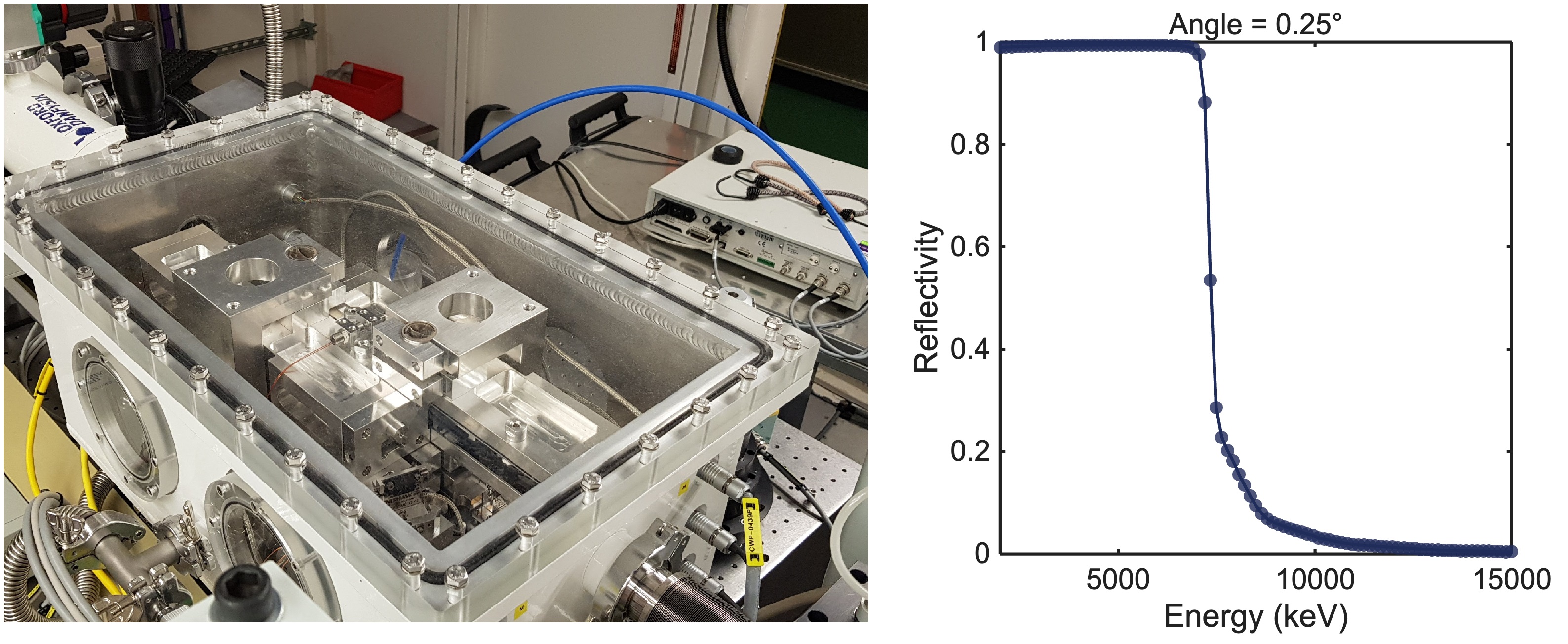
Harmonics arising from the monochromator are suppressed initially using the main focusing mirrors. By selecting either the Rh strip or uncoated Silicon on these mirrors, a reasonable degree of harmonic rejection is achievable.
For almost complete harmonic rejection, an additional set of Si-based, B4C coated (50 nm) flat mirrors can be automatically installed near the sample position. These horizontal deflection mirrors, denoted the "mini mirrors", can be rotated depending on the incident energy such that the reflectivity is close to 1 for the desired energy and less than 10-2 at energies corresponding to the second and third harmonics of the monochromator.
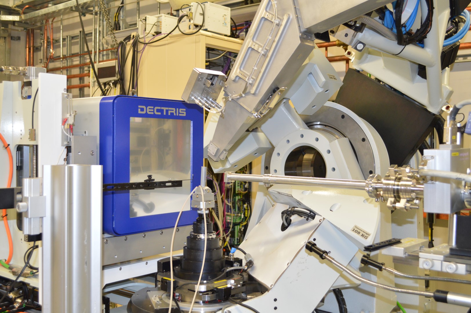
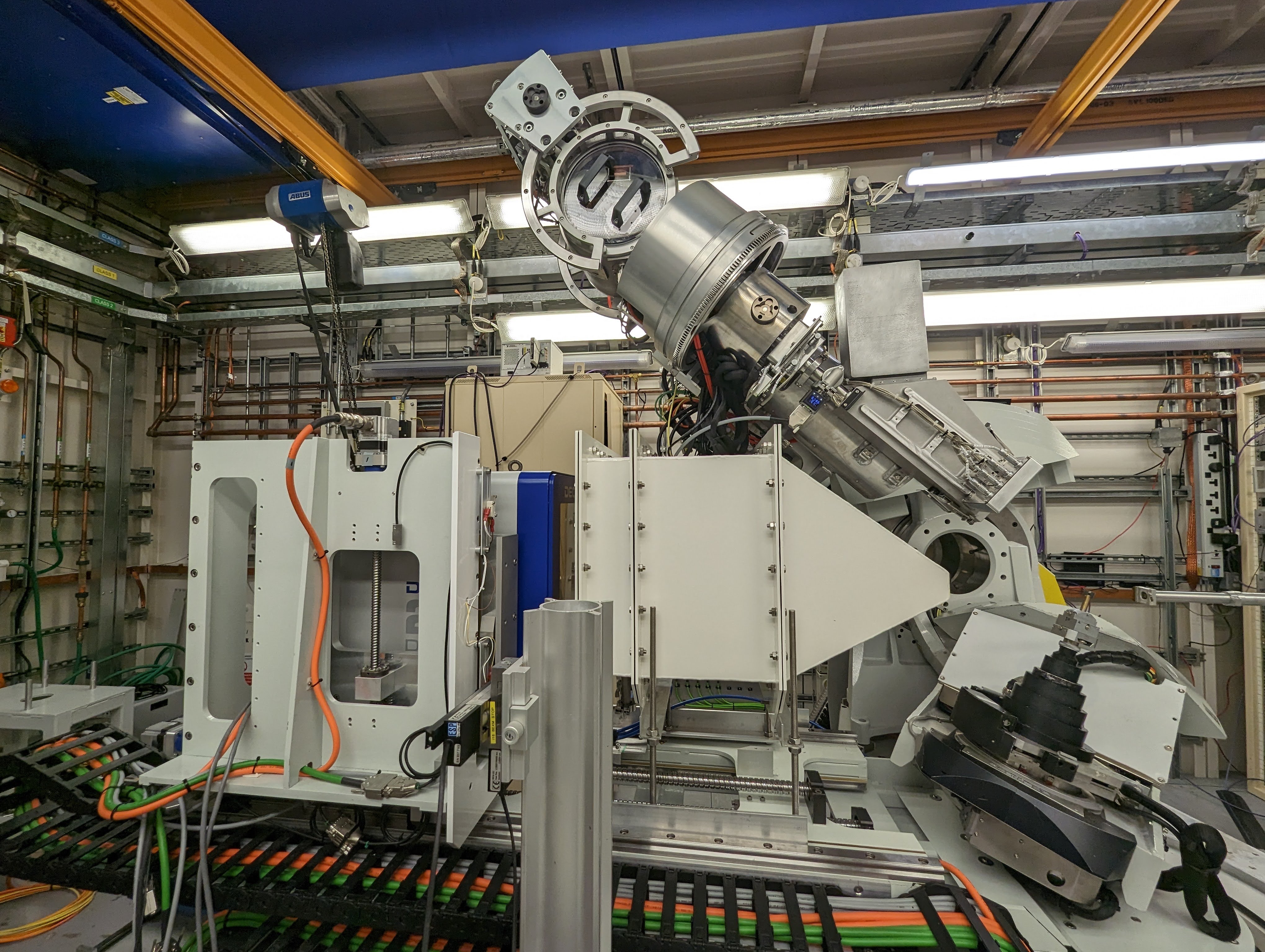
6-Axis Kappa Diffractometer
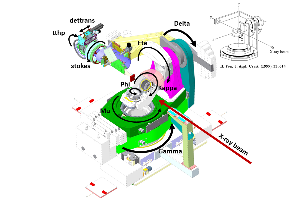
- The I16 Kappa-geometry 6 circle diffractometer
The I16 diffractometer is a 6-circle kappa geometry diffractometer, capable of aligning a sample in any orientation relative to the incident beam.
The large sample space provides space to fit a wide range of sample environments including cryostats, fields and various detectors.
We use a eulerian geometry to drive the sample and detector positions, however these are not always the true motors, for example Chi is a composite of real motors kappa and kphi.
In GDA it is possible to drive the diffractometer using standard Eulerian angles, with the naming convention shown below:
|
|
Description |
Limits (conservative) |
|---|---|---|
| chi | composite angle perpendicular to beam | 98 - -90 Deg |
| eta | sample rotation || to beam, vertical | -20-120 Deg & < Delta |
| delta | detector arm, verticle, depends on pos do | 0-130 Deg |
| phi | sample rotation, kphi is real motor | 0-360 Deg |
| gamma | detector arm, horizontal | 0-130 Deg |
| mu | sample rotation, horizontal | 0-100 Deg & < gam |
We typically operate the diffratometer in one of two geometries - Vertical or Horizontal, however alternative geometries are possible, for example grazing incidence.
We use DiffCalc to drive the diffractometer directly in reciprocal space, allowing a large number of movement modes including - fixed phi, bisecting, fixed alpha, fixed psi (azimuth).
Read more about the diffractometer: I16 6-axis Diffractometer
Polarisation Analyser
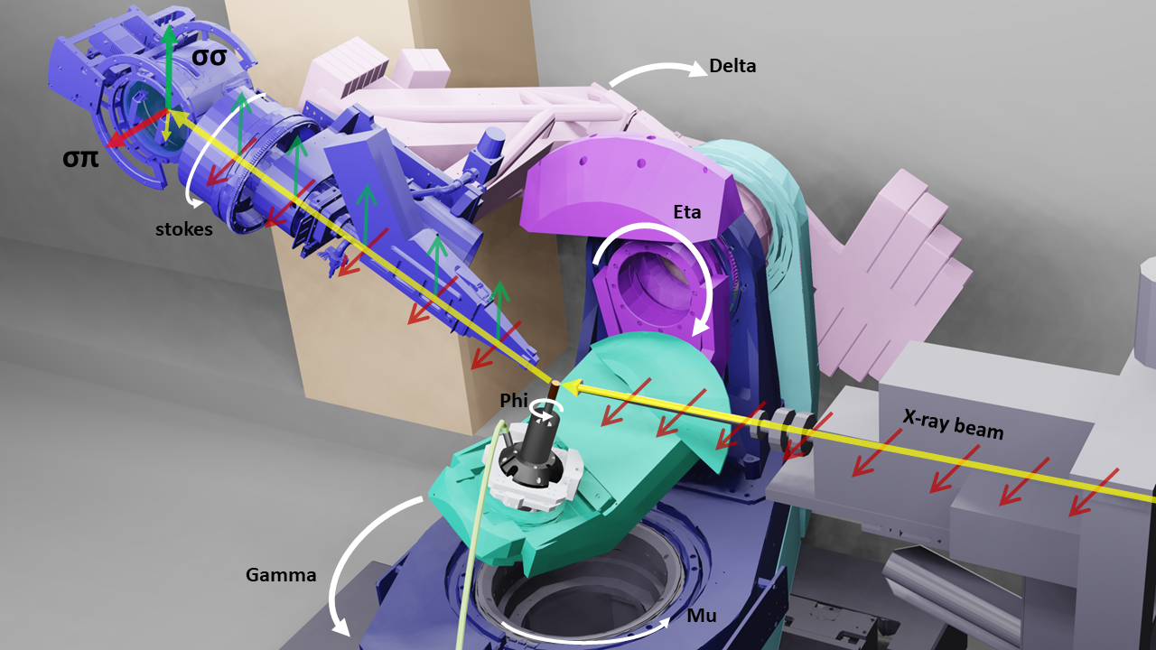
A polarisation analyser stage is fitted to the detector arm with 360 degrees of motion from -180 to 180 degrees about the scattered beam. A selection of different analyser crystals are availble depending on what energy and crystal mosaic are required.

Read more about the polarisation analysers here: Polarisation Control and Analysis
Photon-counting area detector - Pilatus3 100K
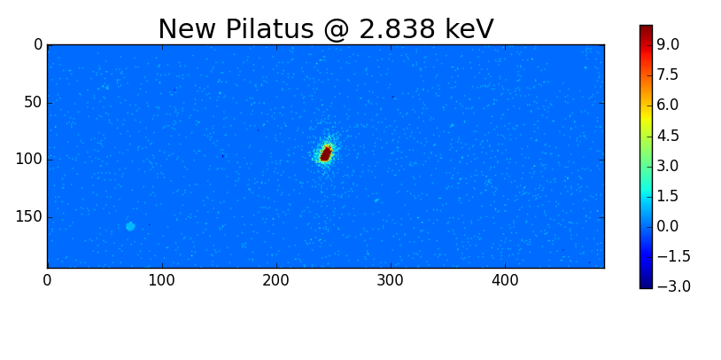
The Pilatus3 100K is our workhorse detector used for the majority of measurements. The detector is in-vacuum and has an ultra-high gain option for low energy measurements. The detector is mounted on the detector arm ~8 degrees above the analyser crystal, alowing us to easily switch between different detectors.
Pilatus Geometry
|
Name |
Value |
|---|---|
| Pixel size | 172 x 172 um^2 |
| Detector pixels | 195 (horiz) x 487 (vert) |
| Distance to sample | 565 mm |
| Detector rotation | 35 deg |
| Pixel angular step (Delta) | 0.014 deg |
| Pixel angular step (gamma) | 0.017 deg |
| Detector chi coverage (vertical 20deg) | ~8deg |
| Detector chi coverage (vertical 90deg) | ~3deg |
| Detector delta coverage (vertical) | 6.8 deg |
| Detector gamma coverage (horizontal) | 3.3 deg |
Photon-counting area detector for coherent diffraction - QuadMerlin
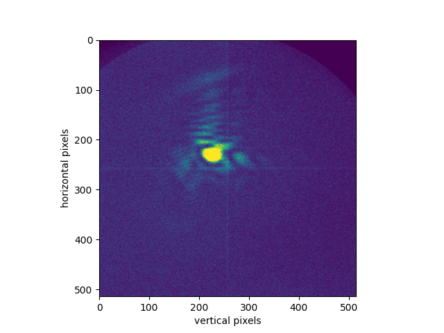
Quad Merlin detector inside PA vessel on I16. The detector is 1,310 mm from the sample and 60 mm from the analyser crystal.
Merlin Geometry
| Detector Type | Merlin |
|---|---|
| Detector make | Quantum Detectors |
| Pixels | 515 x 515 |
| Pixel Size | 55 x 55 um |
| Max count rate (per pixel per s) | 100,000 |
|
Max exposure counts (per pixel per exposure) |
12-bit: 4096 24-bit: 16,777,216 |
| Detector distance (sample) | 1310 mm |
| Detector distance (analyser) | 60 mm |
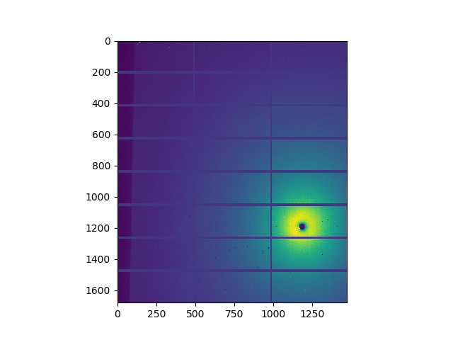
Large Area Detector: Pilatus 2M
This large area detector sits on an extending table to control the detector distance. Horizontal and vertical alignment is possible on the table, and the table can be manually rotated around the gamma-axis of the diffractometer.
Additional options for the Pilatus 2M include a flight tube and beam stop.
Pilatus 2M Geometry
|
Name |
Value |
|---|---|
| Pixel size | 172 x 172 um^2 |
| Detector pixels | 1475 (horiz) x 1679 (vert) |
| Number of modules | 3 x 8 |
| Area | 254 x 289 mm2 |
| Max count rate | 107 ph/s/pixel |
| Distance to sample | ~500 - 2000 mm |
Detector image
Flight Tube
Navigation
If you have any comments, suggestions or corrections, please contact a member of the beamline staff.

Diamond Light Source is the UK's national synchrotron science facility, located at the Harwell Science and Innovation Campus in Oxfordshire.
Diamond Light Source Ltd
Diamond House
Harwell Science & Innovation Campus
Didcot
Oxfordshire
OX11 0DE
Copyright © Diamond Light Source. Diamond Light Source® and the Diamond logo are registered trademarks of Diamond Light Source Ltd
Registered in England and Wales at Diamond House, Harwell Science and Innovation Campus, Didcot, Oxfordshire, OX11 0DE, United Kingdom. Company number: 4375679. VAT number: 287 461 957. Economic Operators Registration and Identification (EORI) number: GB287461957003.