Instruments by Science Group
I16 Contact
Beamline Phone Number:
+44 (0) 1235 778616
Principal Beamline Scientist:
Alessandro Bombardi
Tel: +44 (0) 1235 778226
E-mail: [email protected]
I16 Materials and Magnetism
Status: Operational
Energy: 2.7 - 15 keV
Imaging
Spectroscopy
X-ray Diffraction
WAXS: Wide Angle X-ray Scattering
X-ray Single Crystal Diffraction
High Pressure
Scattering
Bragg CDI
CDI: Coherent Diffraction Imaging
Ptychography
GIWAXS: Grazing Incidence WAXS
SXRD: Surface X-ray Diffraction
Spectroscopy
XMLD: X-Ray Magnetic Linear Dichroism
XMCD: X-ray Magnetic Circular Dichroism
XRR: X-ray Reflectivity
REXS: Resonant Elastic X-ray Scattering
- Diffractometer
- Cryostats
- Pilatus3 100K
- QuadMerlin Detector
- Pilatus 2M
- Electric Fields
- Magnetic Fields
- Strain
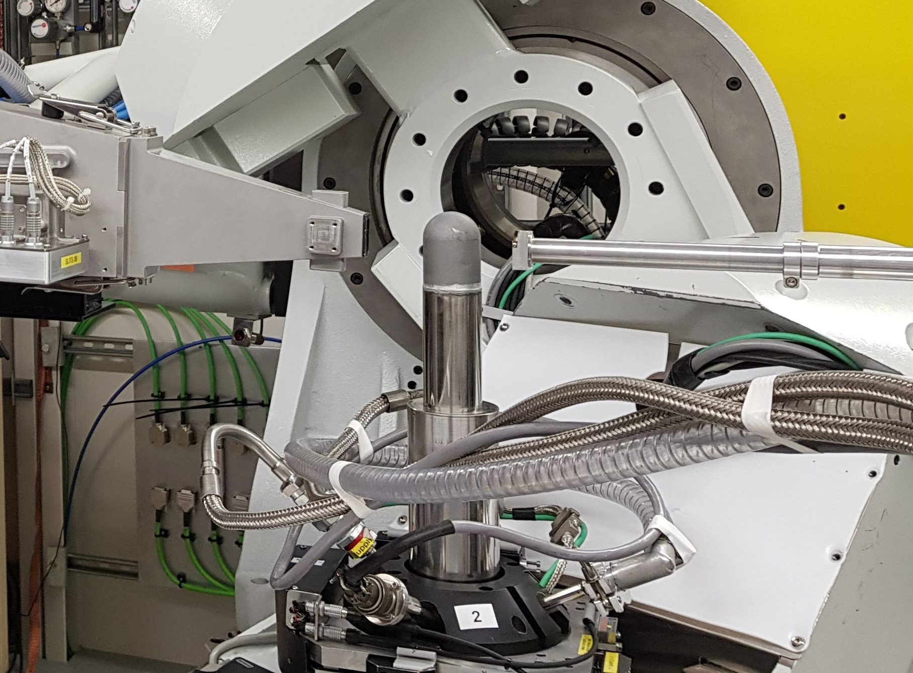
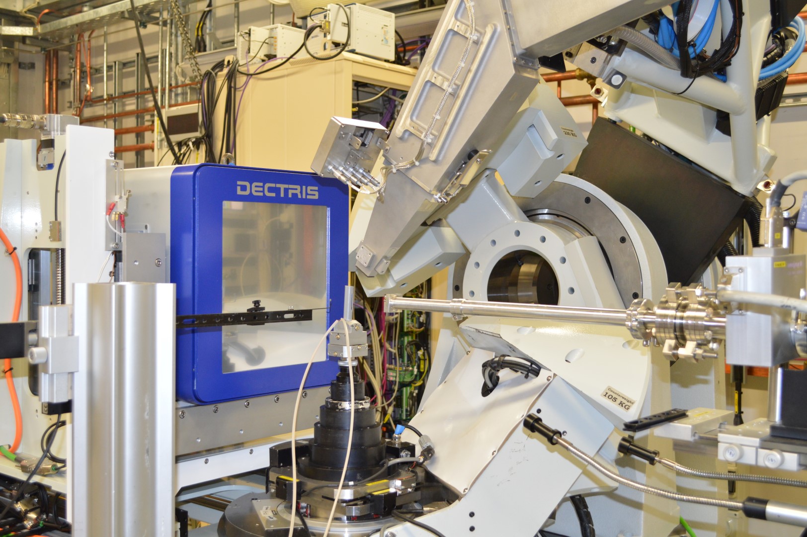
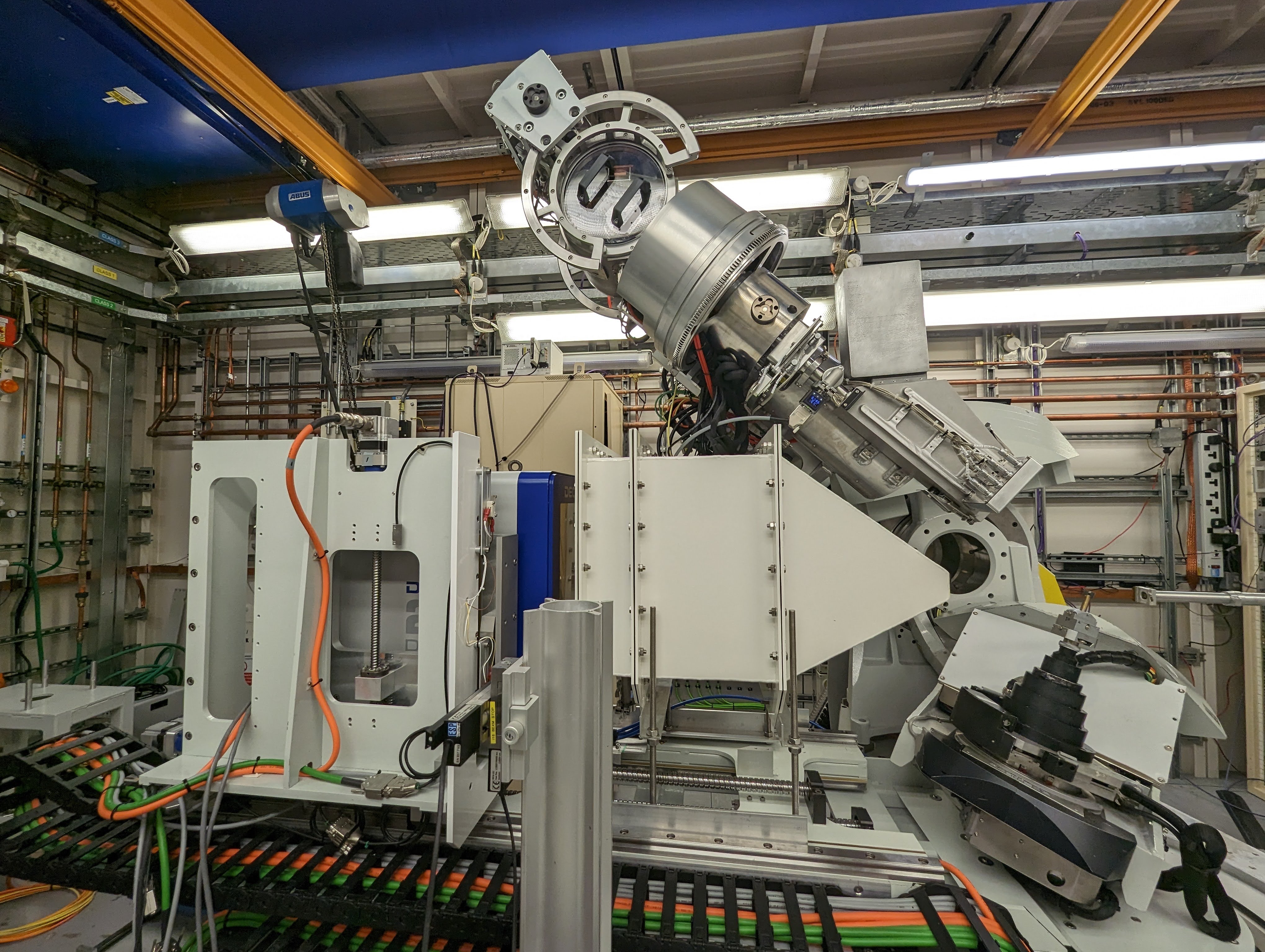
6-Axis Kappa Diffractometer
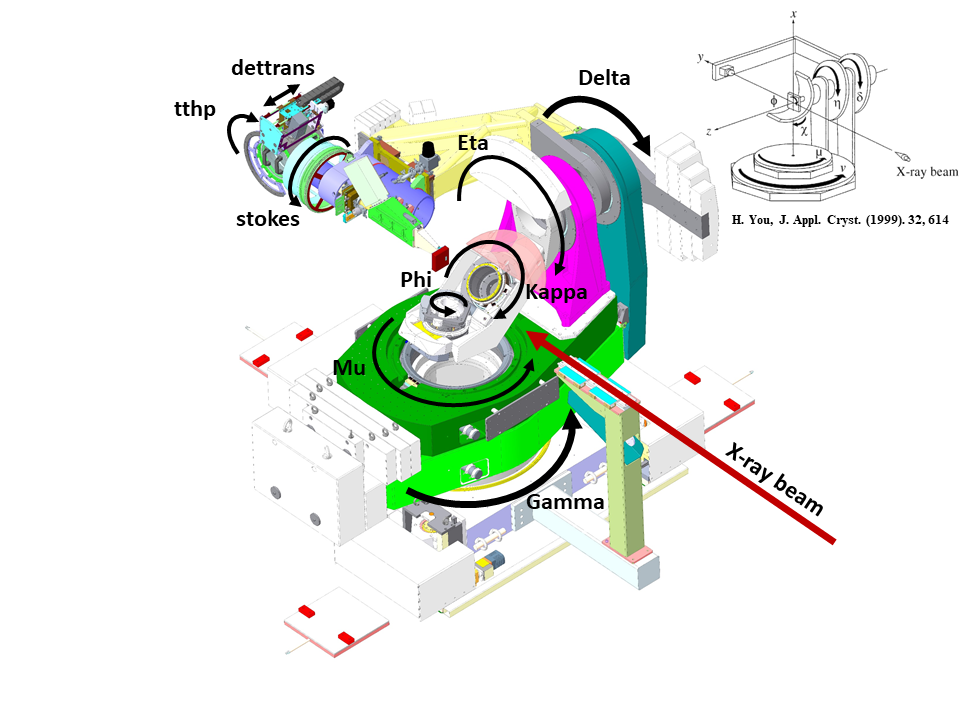
- The I16 Kappa-geometry 6 circle diffractometer
The I16 diffractometer is a 6-circle kappa geometry diffractometer, capable of aligning a sample in any orientation relative to the incident beam.
The large sample space provides space to fit a wide range of sample environments including cryostats, fields and various detectors.
We use a eulerian geometry to drive the sample and detector positions, however these are not always the true motors, for example Chi is a composite of real motors kappa and kphi.
In GDA it is possible to drive the diffractometer using standard Eulerian angles, with the naming convention shown below:
|
|
Description |
Limits (conservative) |
|---|---|---|
| chi | composite angle perpendicular to beam | 98 - -90 Deg |
| eta | sample rotation || to beam, vertical | -20-120 Deg & < Delta |
| delta | detector arm, verticle, depends on pos do | 0-130 Deg |
| phi | sample rotation, kphi is real motor | 0-360 Deg |
| gamma | detector arm, horizontal | 0-130 Deg |
| mu | sample rotation, horizontal | 0-100 Deg & < gam |
We typically operate the diffratometer in one of two geometries - Vertical or Horizontal, however alternative geometries are possible, for example grazing incidence.
We use DiffCalc to drive the diffractometer directly in reciprocal space, allowing a large number of movement modes including - fixed phi, bisecting, fixed alpha, fixed psi (azimuth).
Read more about the diffractometer: I16 6-axis Diffractometer
Cryostats
Technical Specifications
|
ARS Cryocooler |
DE-202SK (Cryostat) |
DE-202AK (Cryofurnace) |
DE-202SK (New Cryostat) |
|---|---|---|---|
| Cooling Capacity | 0.1W (4.2K) | 0.5W (10K) | 0.1W (4.2K) |
| Compressor | ARS-4HW | ARS-4HW | ARS-4HW |
| Base Temperature | < 6 K | < 10 K | < 6 K |
| Max Temperature | 300K | 800K | 300K |
For studies requiring ultra low vibrations (i.e. coherent diffraction) , a ColdEdge Stinger cryostat system is readily available. Please contact beamline staff if you would like to explore this option.
|
ColdEdge |
Stinger (Cryostat) |
|---|---|
| Compressor | Stinger + F-70 Sumitomo |
| Base Temperature | < 5.2 K |
| Max Temperature | 300K |
Photon-counting area detector - Pilatus3 100K
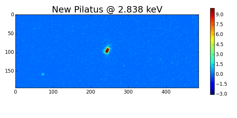
The Pilatus3 100K is our workhorse detector used for the majority of measurements. The detector is in-vacuum and has an ultra-high gain option for low energy measurements. The detector is mounted on the detector arm ~8 degrees above the analyser crystal, alowing us to easily switch between different detectors.
Pilatus Geometry
|
Name |
Value |
|---|---|
| Pixel size | 172 x 172 um^2 |
| Detector pixels | 195 (horiz) x 487 (vert) |
| Distance to sample | 565 mm |
| Detector rotation | 35 deg |
| Pixel angular step (Delta) | 0.014 deg |
| Pixel angular step (gamma) | 0.017 deg |
| Detector chi coverage (vertical 20deg) | ~8deg |
| Detector chi coverage (vertical 90deg) | ~3deg |
| Detector delta coverage (vertical) | 6.8 deg |
| Detector gamma coverage (horizontal) | 3.3 deg |
Photon-counting area detector for coherent diffraction - QuadMerlin
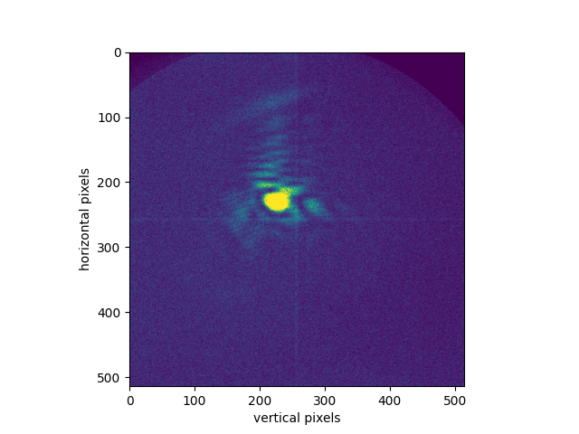
Quad Merlin detector inside PA vessel on I16. The detector is 1,310 mm from the sample and 60 mm from the analyser crystal.
Merlin Geometry
| Detector Type | Merlin |
|---|---|
| Detector make | Quantum Detectors |
| Pixels | 515 x 515 |
| Pixel Size | 55 x 55 um |
| Max count rate (per pixel per s) | 100,000 |
|
Max exposure counts (per pixel per exposure) |
12-bit: 4096 24-bit: 16,777,216 |
| Detector distance (sample) | 1310 mm |
| Detector distance (analyser) | 60 mm |
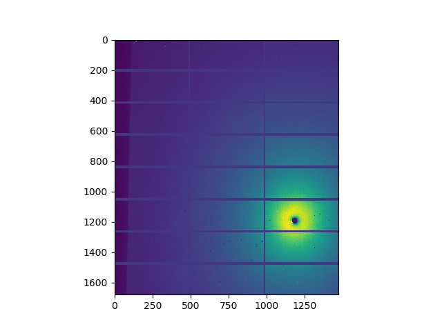
Large Area Detector: Pilatus 2M
This large area detector sits on an extending table to control the detector distance. Horizontal and vertical alignment is possible on the table, and the table can be manually rotated around the gamma-axis of the diffractometer.
Additional options for the Pilatus 2M include a flight tube and beam stop.
Pilatus 2M Geometry
|
Name |
Value |
|---|---|
| Pixel size | 172 x 172 um^2 |
| Detector pixels | 1475 (horiz) x 1679 (vert) |
| Number of modules | 3 x 8 |
| Area | 254 x 289 mm2 |
| Max count rate | 107 ph/s/pixel |
| Distance to sample | ~500 - 2000 mm |
Detector image
Flight Tube
Electric Fields
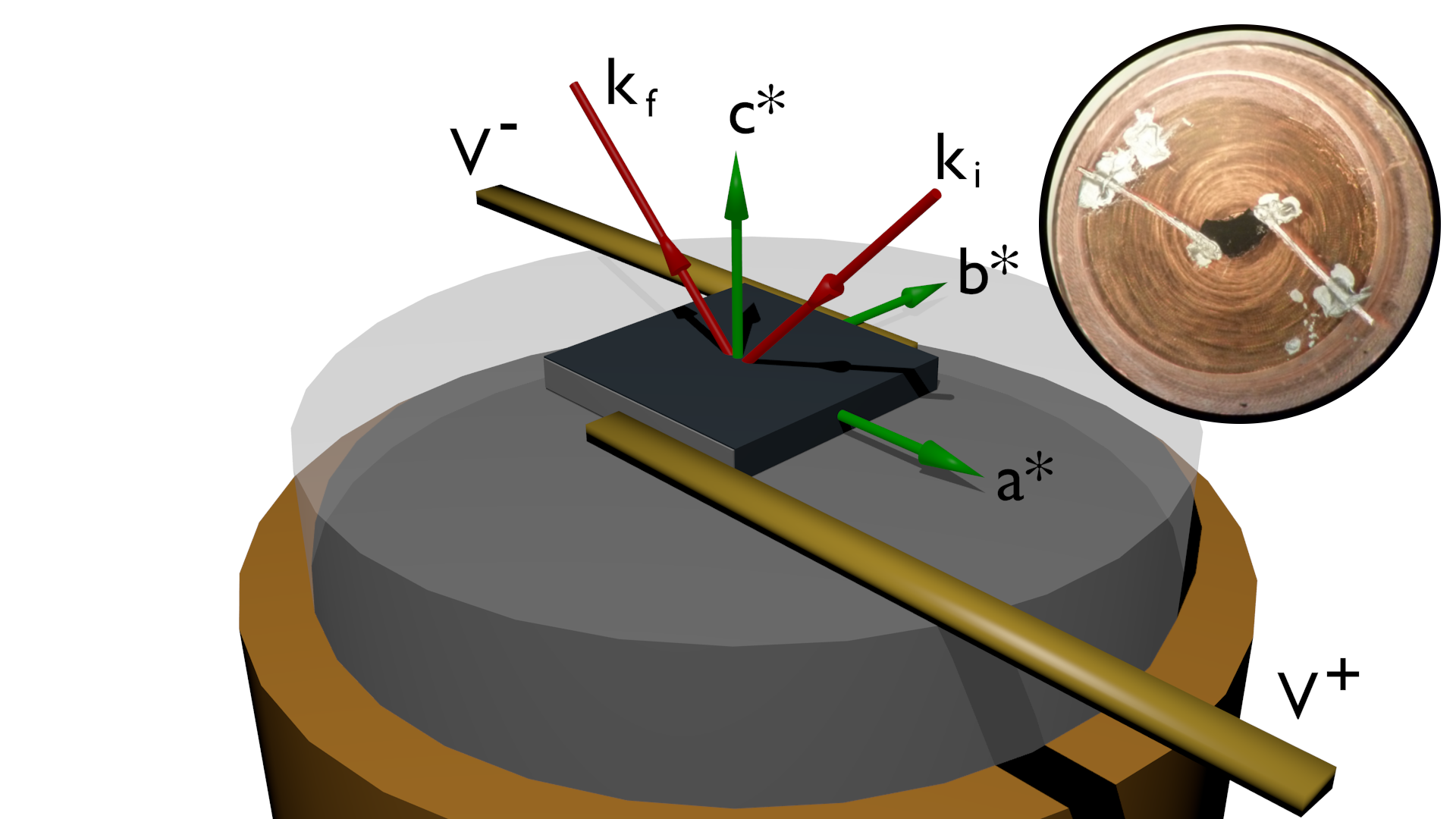
- Illustration and inset-example of sample mounted with electric contacts in scattering geometry
Power supplies available
- Keithley 1100V source-meter (model 2410)
- Trek 10 kV amplifier (model 610A)
- Agilent waveform generator (model 33220A)
Specifications: Keithley 2410 1100V Source meter
| Attribute | Value |
|---|---|
| Series | 2400 |
|
Sourcemeter Function |
Current Resistance Voltage Measure, Current Voltage Source |
| Number of Channels | 1 |
| Source Voltage Range | ±200 mV → ±1000 V |
| Source Current Range | ±1 μA → ±1 A |
| Output Power | 22 W |
| Resistance Measurement Range | 0.2 Ω → 200 MΩ |
Specifications: Agilent 33220A Arbitary waveform generator
| Min | Max | |
|---|---|---|
| Frequency | 1 uHz | 20 MHz |
| Voltage amplitude | 10 mV | 10V peak-to-peak |
| Voltage offset | 0 | 4.95 V |
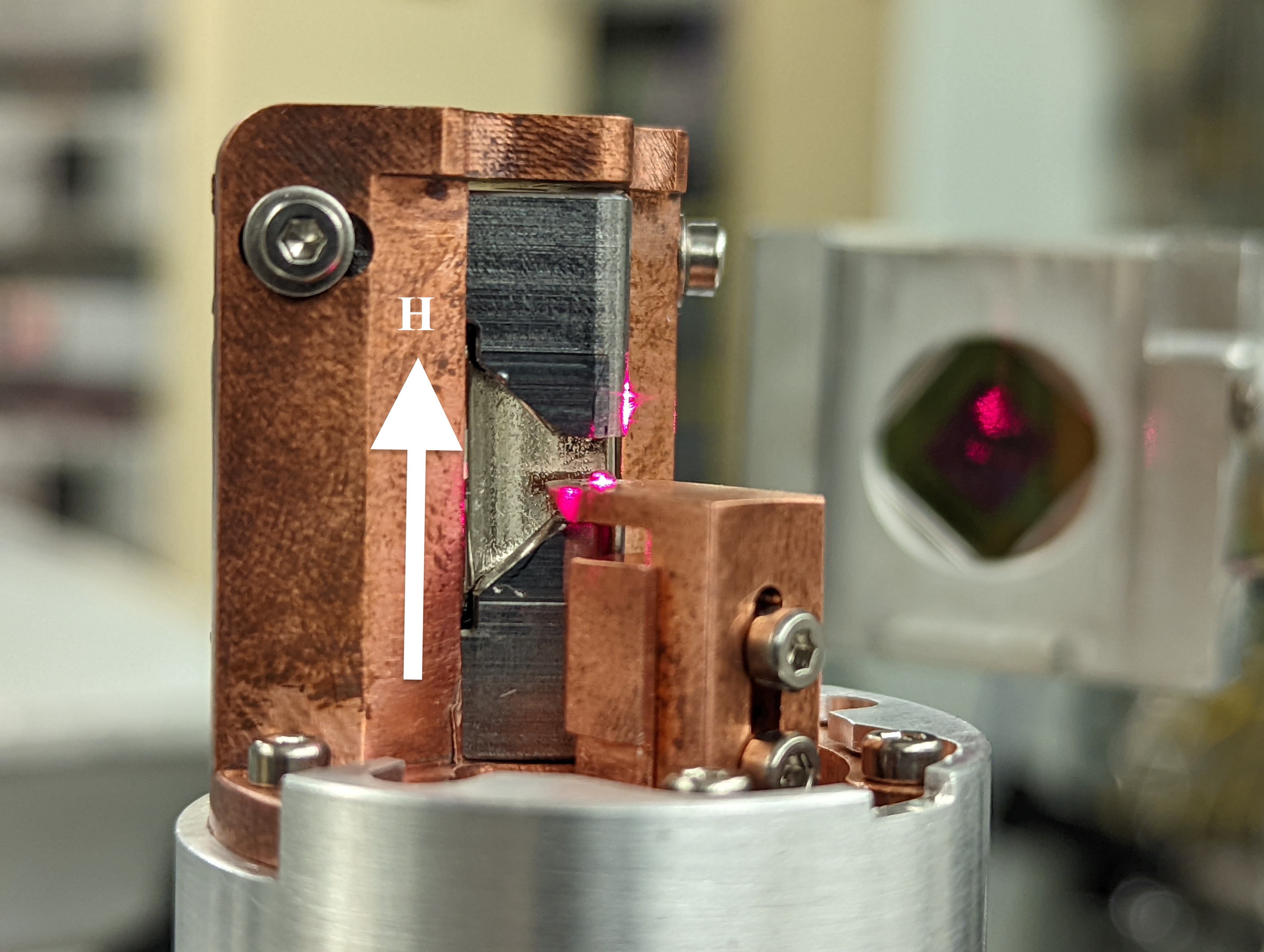
Magnetic Fields
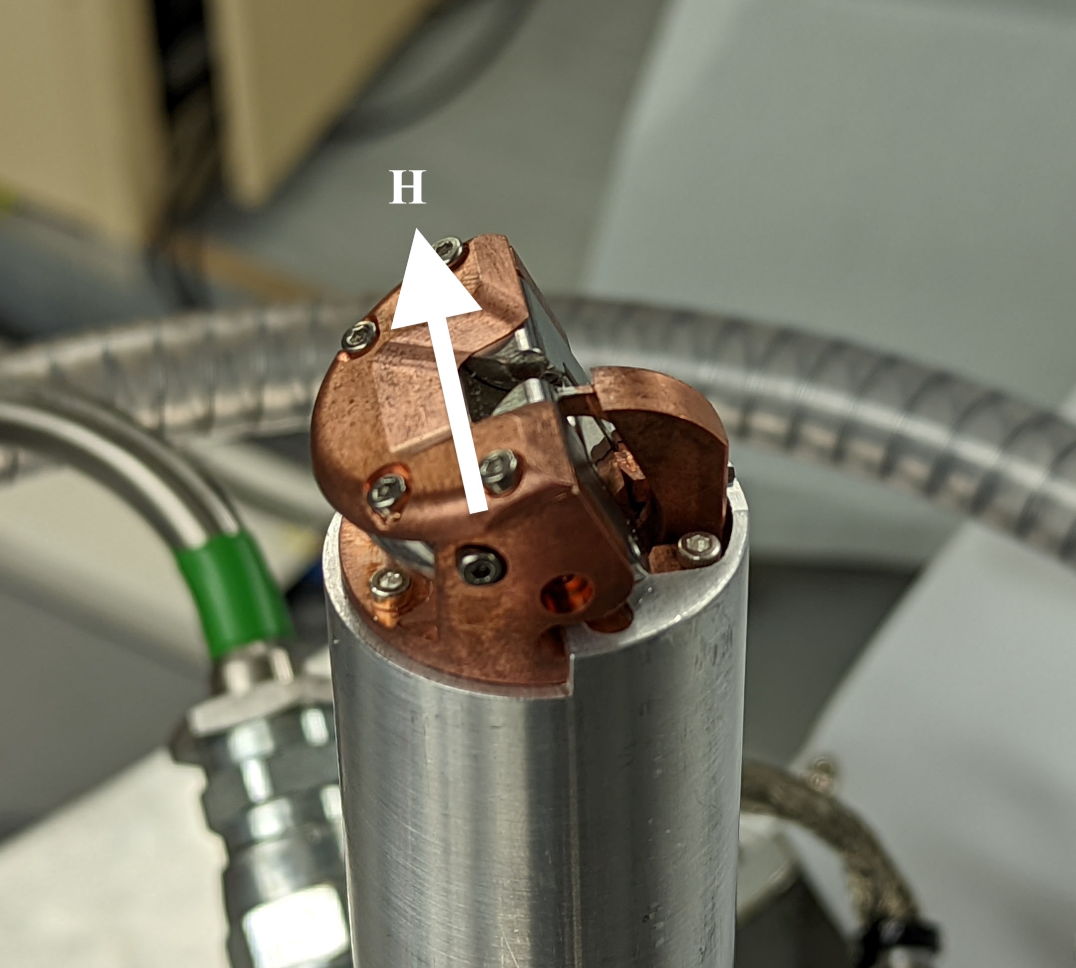
Permanent magnets developed in collaboration with STFC are available and provide fields of up to 1 T with a large reciprocal space access. The magnets are available in two different geometries: horizontal and vertical. The horizontal holder applies a field parallel to the horizontal scattering plane, and the vertical holder a field parallel to the vertical scattering plane. The magnets were designed to fit underneath the Be domes, and so can provide the necessary fields in combination with cryogenic temperatures (5 K). Magnets with fields of 1 T and 0.8 T are available and have gaps of 3 mm and 4 mm respectively in which the sample can be mounted. The magnets are grade N52, made of NdFeB, which have a phase transition around 320 °C.
Uniaxial-Strain
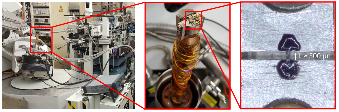
- A sample mounted on the Razorbill CS100 insitu strain cell, mounted on the cryostat on I16.
Using a Razorbill CS100 strain cell, we have the ability on I16 to measure x-ray diffraction, including resonant and magnetic scattering, from samples while applying tensile and compressive uniaxial strain, even at cryogenic temperatures. The high angular resolution of I16 provides accurate determination of the strain based on diffraction measurements. In particular it is possible to use reciprocal space mapping to watch the change in Bragg peak shape under strain. A full range of resonant measurements is possible, including polarisation control and analysis, energy scanning and azimuthal scans. Sample are typically mounted in reflection geometry on the strain cell and adhered using Stycast or another hard epoxy resin.
The specifications for this device are given in the table below:
|
Razorbill CS100 |
|
|
Dimensions |
Diameter 24 mm, Height 13 mm |
|
Maximum displacement |
+/- 3 μm (4K), +/- 6 μm (300K) |
|
Maximum force |
+/- 45 N |
|
Maximum spring constant |
5x10⁶ N/m |
|
Ideal sample size |
Length: 2000 μm along strain direction |
|
|
Width: 300 μm (sample surface) |
|
|
Thickness: 200 μm |
|
Temperature range (on I16 cryostat) |
10 – 300K |
On I16, the strain cell is mounted on the ARS cryocooler, providing cooling to <10K. The cold head operates in-vacuum with a Beryllium dome for x-ray transmission in reflection geometry. This geometry provides maximum access for the incident and scattered x-ray beam in a range of scattering geometries. The cell’s power supply and measurement of the cell capacitance (to determine relative displacement) have been implemented into the beamline software allowing full strain/ temperature phase maps to be automated.
We additionally offer the MC051 Razorbill mechanical strain cells with 800 μm and 500 μm gaps.
Navigation
If you have any comments, suggestions or corrections, please contact a member of the beamline staff.

Diamond Light Source is the UK's national synchrotron science facility, located at the Harwell Science and Innovation Campus in Oxfordshire.
Diamond Light Source Ltd
Diamond House
Harwell Science & Innovation Campus
Didcot
Oxfordshire
OX11 0DE
Copyright © Diamond Light Source. Diamond Light Source® and the Diamond logo are registered trademarks of Diamond Light Source Ltd
Registered in England and Wales at Diamond House, Harwell Science and Innovation Campus, Didcot, Oxfordshire, OX11 0DE, United Kingdom. Company number: 4375679. VAT number: 287 461 957. Economic Operators Registration and Identification (EORI) number: GB287461957003.