Crystal Orientation Calculations
STAC
The STAC software can be started by typing the command "stac" in a Unix terminal. Quite often it doesn't start smoothly at the first attempt. Killing the process with CTRL-C and then restarting STAC is the recommended procedure. Once the software is started it comes up with a main window and a small job control window. The main window is organised in different tabs:
Motor Access: Allows to control the rotations omega, kappa, phi and the sample centring stages gonx, samy, samz plus an option to tilt the crystal
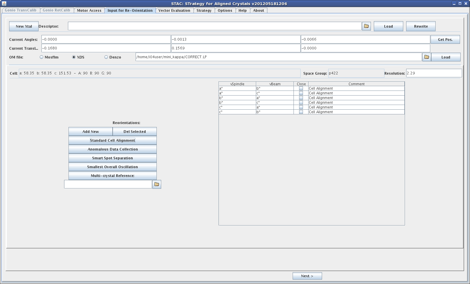
Input for Re-orientation: This is where calculation tasks are defined
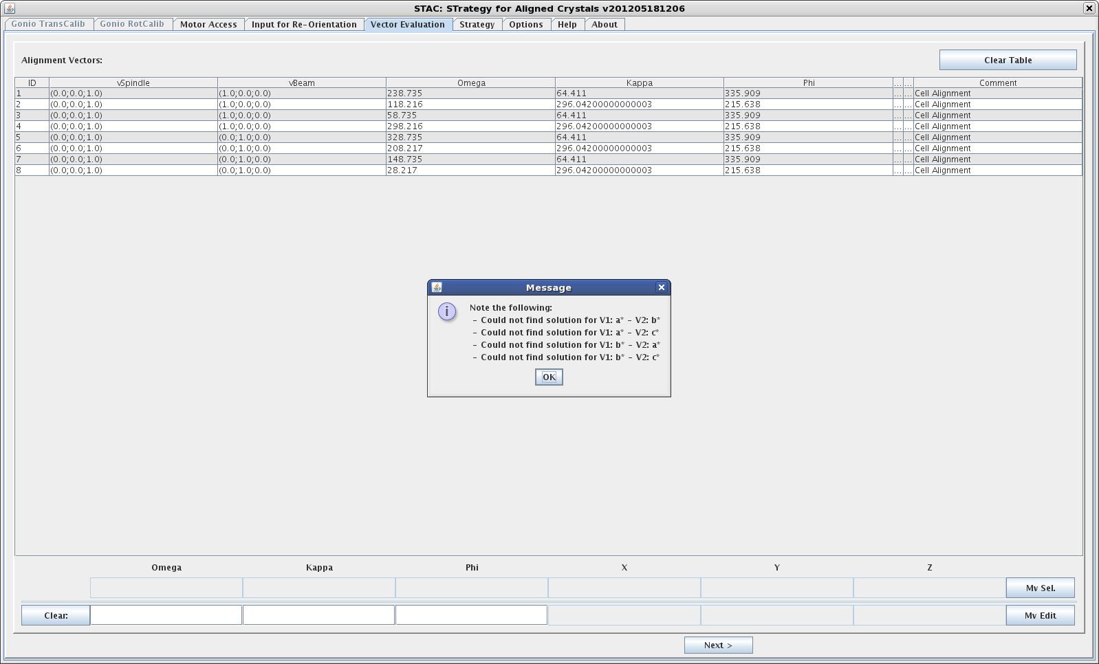
Vector Evaluation: This tab shows the results of orientation calculations
Strategy: If a strategy at a certain orientation is requested the results will be shown here
Orientation Calculations
- Select the "Input for Re-orientation" tab
- Get the current goniometer positions by clicking the "get Pos." button; this will fill in the values for the current angles and translations
- Select an orientation matrix file using the browser icon. STAC can read the following files
- bestfile.par (mosflm)
- CORRECT.LP (XDS)
- file.x (denzo)
CORRECT.LP can be found in the fast_dp or xia2 directories - Load the orientation matrix file by clicking the "Load" button. This will populate the Cell, Space Group and Resolution fields below. Check that the information is correct.
- Select one of the calculation options, like "Standard Cell Alignment" by clicking the corresponding button. This will populate the table on the right
- Click the "Next" button. This will start the calculation and switch to the "Vector Evaluation" tab where the results can be analysed
Calculation options
STAC provides the following calculation options:
- Standard Cell Alignment
This option calculates orientations for reciprocal unit cell axes a*, b*, c* along the rotation axis (vSpindle) or beam direction (vBeam). Arbitrary Miller indices (h, k, l) or real space vectors [a, b, c] can also be used. - Anomalous Data Collection
This option calculates a crystal orientation where Bijvoet pairs can be measured on the same image, e.g. along a fourfold axis in the tetragonal lattice system. - Smart Spot Separation
This option calculates a crystal orientation which minimises spot overlap, a problem that occurs especially with long unit cell axes. - Smallest Overall Oscillation
This option calculates a crystal orientation where the total overall oscillation range is reduce, e.g. from 90 to 45 deg in a tetragonal system. This can be useful to reduce
effects of radiation damage. - Multi-crystal Reference
Using the file browser icon an orientation matrix of a previously measured crystal can be loaded. This information is then used to orient the new sample in exactly the same
orientation as the previous sample. This is useful when it wasn't possible to collect a complete data set of the previous sample. Using a known orientation allows to collect
data from the new sample that hasn't been collected before. A record of the omega rotation range for the previous sample is required to avoid data overlap.
Sometimes an exact orientation cannot be calculated. In this case the user can tick the "Close" tickbox. STAC will then try to calculate a solution that is close to the requested input,
e.g. (0.95, 0, 0) instead of (1, 0, 0).
Examples of input options are given below
Calculation Results
Calculation results are presented in the "Vector Evaluation" tab. Sometimes there is a pop-up window indicating the cases for which no solution could be found. The results are presented in a table.
- ID
A numeric label for each solution - vSpindle
Direction of the rotation axis. Solution vectors are given in component notation. E.g. (0.0, 0.0, 1.0) means that the c* axis is aligned along the rotation axis. - Beam direction. Solution vectors are given in component notation. E.g. (1.0, 0.0, 0.0) means that the a* axis is aligned along the beam.
- Omega
Omega start angle for a given solution - Kappa
Kappa angle for a given orientation - Phi
Phi angle for a given orientation - Comment
Indicates which calculation option has been requested
An example screenshot is given below
Strategies
STAC can calculate data collection strategies based on a chosen orientation solution. These are purely geometric, biased towards completeness, and don't take into account any other sample information. Use of this option is therefore discouraged.
Work is in progress to provide better strategies when using the mini kappa. An automatic workflow is also under development.
