Where do metals diffuse inside a nanoparticle?

Nanoparticles exhibit excess surface free energy and structural instabilities, which leads to interesting chemical and physical properties that can be exploited in fields such as semiconductors and catalysis. The question of atomic diffusion in nanoparticles, a thermallyactivated mixing process, has remained unanswered for many years due to an inability to image the crystals in three dimensions in their ‘as-grown’ in situ environment. X-ray diffraction can play an important role in unveiling atomic behaviours of nanoparticles in three dimensions. Bragg Coherent Diffraction Imaging (BCDI) converts a 3D diffraction pattern into real space 3D images of the crystal, yielding highly sensitive detection of the very small lattice distortions in nanocrystals. The Surface and Interface Diffraction beamline (I07) at Diamond Light Source allowed observation of the evolution of the structure of a single nanocrystal after exposure to a second metal. Copper (Cu) was diffused into a gold (Au) nanocrystal by heating under vacuum in the ultra-high vacuum end station of I07, which provides extremely coherent X-rays for BCDI. High temperature promoted the mixing of the metals, and the diffusion process was followed by studying the size, shape, and lattice, surface and interface effects for an individual nanocrystal, removing the need to measure and average signals from a large area. Images from this study show enhanced diffusion where Cu enters the surface of the gold nanocrystal, starting preferentially from the crystal edges. Dislocation loops are formed where a single layer of atoms, consisting of Cu atoms, Au atoms, or a mixture, is inserted over a small region between two existing planes. With its high sensitivity to lattice displacements, this technique shows great promise for the investigation of atomic behaviour in nanoparticles and the development of novel nanomaterials.

Beamline I07 Scientific Highlight

This question was addressed by Gang Xiong and colleagues at their inaugural experiment on the (then new) second hutch of the I07 beamline, which had been built by the group of Chris Nicklin. The question of where metals diffuse inside a nanoparticle had remained unanswered for many years for want of an in situ crystal imaging system that works fully in three dimensions (3D) at high resolution. The metals concerned, Cu and Au, are relatively inert at room temperature and only start to mix together around 600 °C, which is around three-quarters of their melting point. The design of the second I07 endstation (EH2) provides this capability with its ultra-high vacuum (UHV) sample heater stage and provisions for metal evaporation.

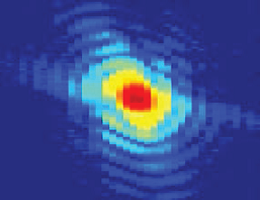
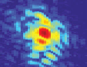
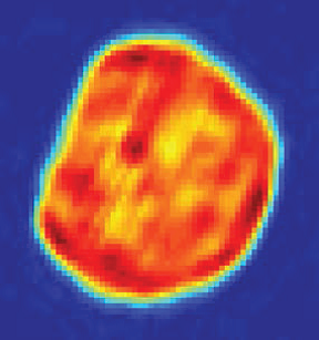
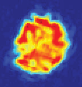
Figure 1: (top left) and (top right) central section of the BCDI diffraction patterns, measured at I07, of the 111 Bragg peak of a gold nanocrystal before and after deposition of copper on top of it at 600 °C; (bottom left) and (bottom right) cross sections through the inverted images obtained from the full 3D diffraction patterns. Scale bar is 100 nm.

X-ray Diffraction (XRD) is a core technique at Diamond, and one of the main justifications for the use of synchrotron radiation is that experiments can be done on extremely small samples, 300 nm in this case. With the focused undulator beam, the diffraction from a single nanocrystal can be recorded on a photon-counting Pilatus detector, mounted on the EH2 diffractometer, in a reasonable amount of time. The experiment used a coherent X-ray beam to resolve the interference fringes from the outer extremities of the crystal. To make the beam coherent, the beam was cut down further (with slits) to a size of around 20 μm and shining it onto an array of nanoparticles mounted in the UHV chamber. Since the crystals were all oriented in different directions, a single one could be isolated by the diffraction pattern surrounding one of its Bragg peaks. This peak was then measured repeatedly by short half-degree rocking curves while the second metal was added to the first by running the evaporator.

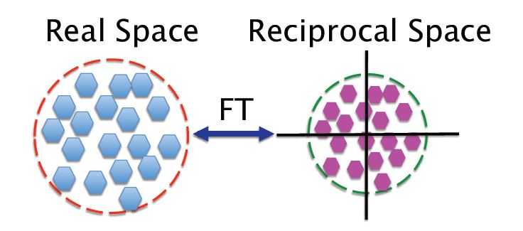
Figure 2: Schematic diffraction pattern (right) of a bounded array of small sub-objects within an enclosed object region (left). The envelope width of the diffraction pattern is the reciprocal of the size of the sub-objects while the speckle size is the reciprocal of the whole ensemble. An immediate consequence of this reciprocity is that the number of speckles is numerically equal to the number of sub-objects in the ensemble. FT denotes Fourier Transform.

Gold nanocrystal samples were prepared by a dewetting procedure starting from an evaporated film, 20 nm thick on a silicon wafer substrate, prepared independently before the I07 experiment. Upon heating this film in a furnace at very high temperature just below the melting point, the Au detached from the surface and beaded up into 300 nanometre-sized cylindrical forms, about 150 nm tall. These beads turned out to be mostly single crystals with occasionally twinned pairs of crystals stuck together. One of these nanocrystal arrays was inserted into the I07 UHV chamber using the load-lock system at the start of the experiment.
Fig. 1a shows a single slice of the 3D coherent diffraction pattern at the beginning of the deposition experiment. At the start of the experiment the diffraction from the crystal had spherical fringes which appeared as concentric circles on the slice shown. Fig. 1b shows how the pattern had evolved after 8 hours of deposition of Cu. It has lost its circular ring structure and has taken on a more speckled appearance. These speckles are well known to be the characteristic diffraction pattern of a disordered array of sub-objects, as illustrated in Fig. 2. In the case of the Au nanocrystal, these sub-objects must be internal blocks (spatial regions) of the crystal which have lost their mutually fixed phase relationship, but retained their crystalline orientation. This situation has arisen from the addition of Cu: both Cu and CuAu alloys have different lattice spacings from Au, so no longer contribute to the diffraction pattern at the Au Bragg peak, effectively disappearing. If inserted into the crystal, it would display phase shifts of the remaining blocks of Au within the particle.

The Bragg Coherent Diffraction Imaging (BCDI) method was developed over the late 1990s and 2000s by the group of Ian Robinson. BCDI converts the 3D diffraction pattern from the rocking curves into real-space 3D images of the crystal. Only when the beam is coherent, are the fringes surrounding the Bragg peak fully resolved; if many crystals were averaged together (as in powder diffraction experiments) or many crystals were superimposed, these fringes would all be washed out and the BCDI experiment would fail. The second requirement for BCDI is that the recording of the fringes must be oversampled on the detector. This point relates to the famous Shannon sampling theorem that says that the complete information about a bandlimited signal is contained in two measurements per period of the signal at its cut-off frequency. Applied here, the Shannon condition means the detector needs to be positioned far enough away from the sample that the recording has at least two pixels per fringe. Once this condition is satisfied, there are sufficient measurement points for the inversion of the diffraction to an image to be a mathematically overdetermined problem, hence can be solved. A variety of BCDI algorithms have been invented which effectively solve this phase problem1.

The resulting images of the Au nanocrystal are shown in Fig. 1c,d, before and after the Cu deposition. The starting crystal has relatively uniform internal density, while the alloyed crystal has become porous. The 3D distribution of channels seen in the alloyed crystal was the new discovery that warranted publication in Scientific Reports in 2014. The channels identify the pathway taken by the Cu as it diffuses inside the Au nanocrystal. The disappearance of the density within these channels could be because of the different lattice constant of the inserted Cu or CuAu alloy, or else it could be regions of misoriented Au that no longer contribute to the Bragg peak. One strength of the BCDI method is that it generates strong contrast between the Bragg diffracting regions and the rest of the sample

Source publication:
Xiong, G., Clark, J. N., Nicklin, C., Rawle, J. & Robinson, I. K. Atomic Diffusion within Individual Gold Nanocrystal. Scientific Reports 4, doi:10.1038/srep06765 (2014).

References:
1. Fienup, J. R. Phase retrieval algorithms - a comparison. Applied Optics 21, 2758-2769 (1982).

Funding acknowledgements:
EP/I022562/1 “Phase modulation technology for X-ray imaging” and ERC Advanced Grant 227711 “Exploration of strains in synthetic nanocrystals”.

Corresponding author:
Professor Ian Robinson, University College London; Research Complex at Harwell; Tongji University, i.robinson@ucl.ac.uk

Diamond Light Source

Diamond Light Source is the UK's national synchrotron science facility, located at the Harwell Science and Innovation Campus in Oxfordshire.

Copyright © 2022 Diamond Light Source


Diamond Light Source Ltd
Diamond House
Harwell Science & Innovation Campus
Didcot
Oxfordshire
OX11 0DE

See on Google Maps

Diamond Light Source® and the Diamond logo are registered trademarks of Diamond Light Source Ltd

Registered in England and Wales at Diamond House, Harwell Science and Innovation Campus, Didcot, Oxfordshire, OX11 0DE, United Kingdom. Company number: 4375679. VAT number: 287 461 957. Economic Operators Registration and Identification (EORI) number: GB287461957003.

feedback