X-ray Birefringence Imaging

Anisotropic materials are those that exhibit chemical or mechanical differences depending on their orientation. A common example of such a material is wood, where the direction of the grain has an impact on the wood’s characteristics. Birefringent materials are optically anisotropic: the refractive index of the material is dependent on the polarisation state of light passing through it. So, by observing the effect on polarised light passing through a birefringent sample, we can establish the nature of the anisotropy within it. Using the polarising optical microscope, this idea has been used extensively over the last century and has had significant impact on many scientific disciplines including mineralogy, crystallography, materials science, and biological sciences. The idea of X-ray Birefringence Imaging (XBI) is analogous to the optical technique, however it allows the possibility of observing local areas of anisotropy on a molecular scale and can be used to look at regional variations in molecular orientations within a material.

Beamline B16 Scientific Highlight

The facilities available on the Test Beamline (B16) at Diamond Light Source have allowed, for the first time, an experiment to be carried out using a largearea linearly polarised X-ray beam and an area detector. This set-up allows mapping of individual regions (domains) within a sample containing different molecular orientations. Experiments reported in Science demonstrate XBI being used successfully in a range of experiments designed to selectively detect the orientations of C-Br bonds in brominated organic solids. The technique was also successful in identifying changes in molecular orientation during phase transitions. It is hoped that XBI be applied as an analytical tool to explore a wide range of materials science problems in the future, as the technique is not limited to crystalline materials and can be applied to any material with an anisotropic distribution of molecular orientations, including liquids and amorphous solids. It also gives the potential to carry out time-resolved studies due to the full-field nature of the technique.

Invented in the 19th Century, the polarising optical microscope has been used extensively since that time to investigate the structural anisotropy of materials. The operation of the polarising optical microscope1,2 is based on the phenomenon of optical birefringence (i.e., the refractive index of an anisotropic material depends on the orientation of the material with respect to the direction of linearly polarised incident radiation). When such a material is viewed in a polarising optical microscope in ‘crossed-polariser’ configuration, the intensity of observed light depends on the orientation of the ‘optic axis’ of the material relative to the direction of polarisation of the incident light. By measuring the intensity of transmitted light for different orientations of the material, the orientation of the optic axis within the material can be established. Furthermore, if the material comprises orientationally distinct domains, the spatial distribution and orientational relationships between the domains may be revealed.

Although X-ray birefringence and optical birefringence share several common characteristics, optical birefringence relates to the anisotropy of the material as a whole (e.g., for a crystal, it depends on the symmetry of the crystal structure) whereas X-ray birefringence, when studied using an X-ray energy close to the absorption edge of a specific type of atom in the material, depends on the local anisotropy in the vicinity of the selected type of atom. As X-ray birefringence depends on the orientational properties of the bonding environment of the X-ray absorbing atom, measurements of the X-ray birefringence of a material have the potential to yield structural information on the local orientational properties of individual molecules and/or bonds.

The phenomenon of X-ray birefringence has been demonstrated only recently3,4,5. These previous studies used a narrowly focused X-ray beam and did not provide spatially resolved mapping of the material. This study proposed, for the first time, an experimental set-up (Fig. 1) that allows X-ray birefringence measurements to be carried out in a spatially resolved imaging mode, using a large-area linearly-polarised incident X-ray beam and an area detector. With this set-up, the X-ray birefringence of the material can be mapped in a spatially resolved manner, with resolution of the order of 10 μm.

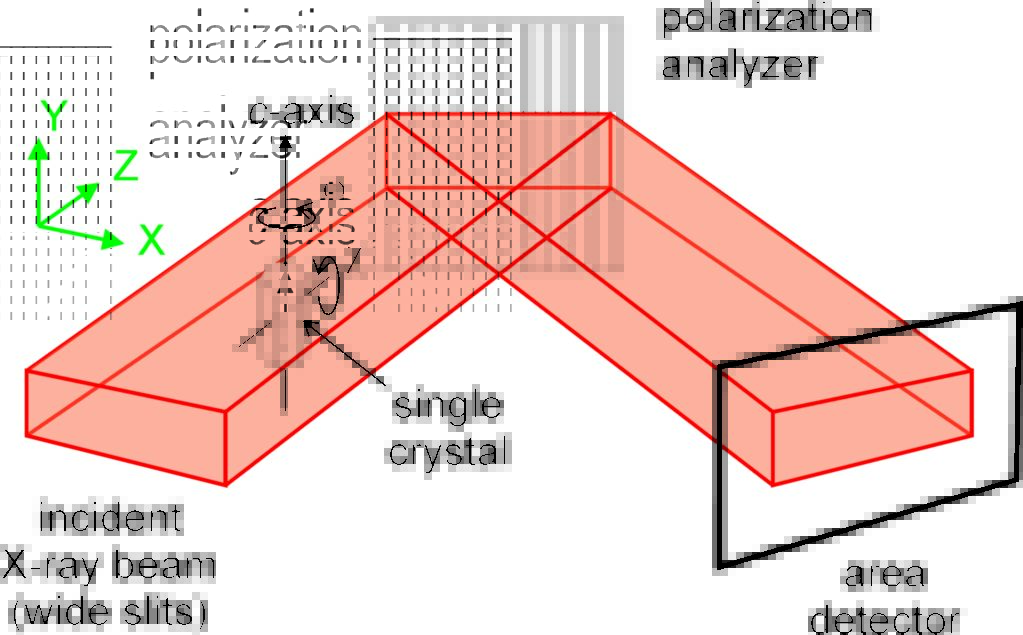
Figure 1: Schematic of the experimental set-up on beamline B16 for X-ray Birefringence Imaging, which exploits linearly polarised X-rays from a synchrotron radiation source.

To demonstrate the new X-ray Birefringence Imaging (XBI) technique, the focus was on materials containing brominated organic molecules, using incident linearly polarised X-rays with energy corresponding to the Br K-edge. In this case, X-ray birefringence depends on the orientation of C–Br bonds relative to the incident polarised X-ray beam. The first XBI experiment in this study investigated a model material (the thiourea inclusion compound containing 1-bromoadamantane [1-BA] guest molecules) in which all C–Br bonds are parallel to each other. Fig. 2 shows X-ray birefringence images for a single crystal of 1-BA/thiourea for different orientations of the crystal (specified by the angle χ). Each image shows a spatially resolved map of the transmitted X-ray intensity (brightness scales proportionally with intensity) for a specific orientation of the crystal. Clearly, the intensity varies significantly as a function of χ, with maximum brightness at χ ≈ 45º and minimum brightness at χ ≈ 90º. Maximum intensity arises when the orientation of the C–Br bonds is at ca. 45º with respect to the direction of linear polarisation of the incident X-ray beam. For each crystal orientation, the transmitted intensity is uniform across the entire crystal, indicating that the crystal comprises a single orientational domain. The observed dependence of intensity on χ is directly analogous to the behaviour of a uni-axial crystal in the polarising optical microscope.

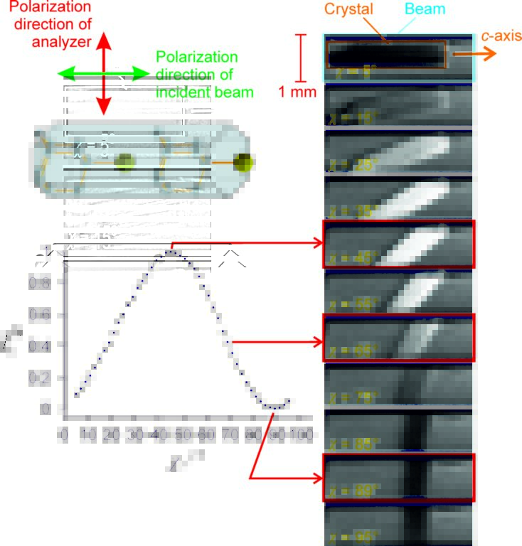
Figure 2: X-ray birefringence images recorded at 280 K for a single crystal of the 1-BA/thiourea inclusion compound (schematic of structure at top left) as a function of crystal orientation. The images are spatially resolved maps of transmitted X-ray intensity across the crystal. Relative brightness in the images scales with X-ray intensity.

To assess the potential to exploit XBI to probe changes in molecular orientational distributions as a function of temperature, experiments were carried out on a single crystal of the thiourea inclusion compound containing bromocyclohexane (BrCH) guest molecules. This material undergoes a phase transition at 233 K from a high-temperature phase in which the orientational distribution of the BrCH guest molecules is isotropic (as a result of rapid molecular motion) to a low-temperature phase in which the BrCH molecules become orientationally ordered. In the low-temperature phase, the XBI data reveal very clearly that the crystal comprises orientationally distinct domains. Thus, in Fig. 3, a large parallelogram-shaped domain (with dimensions of a few hundred μm) dominates the central region of the crystal (bright region in the image), with two smaller domains (dark regions) at each end of the crystal.

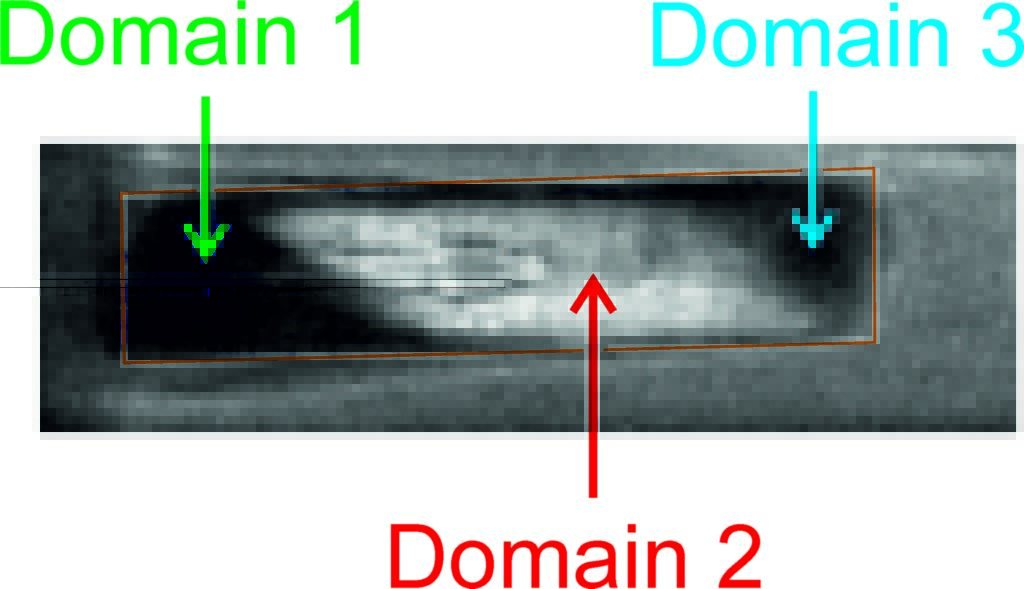
Figure 3: X-ray birefringence image of a single crystal of the BrCH/thiourea inclusion compound at 20 K, showing clear evidence that the crystal comprises orientationally distinct domains (corresponding to regions with differing levels of brightness in the image).

As demonstrated by the results reported in the paper, the new XBI technique enables spatially resolved mapping of the orientational properties of specific types of molecule and/or bond in materials, offering particular opportunities in cases for which the application of X-ray diffraction techniques is not feasible (e.g., partially ordered materials, multiply twinned crystals or other materials with complex domain structures). Although demonstrated in studies of singlecrystal samples, there is no requirement for crystallinity as X-ray birefringence is sensitive specifically to local molecular orientations, so XBI can be applied to any material (including liquids or amorphous solids) with an anisotropic distribution of molecular orientations. The results also reveal the potential to exploit XBI for spatially resolved analysis of orientationally distinct domains, yielding information on domain sizes, the orientational relationships between domains, and the nature of domain boundaries. As XBI is a full-field imaging technique, with the entire image recorded simultaneously, the measurement of X-ray birefringence images can be carried out quickly (exposure time of 1 s for each image shown here) leading to the potential to perform time-resolved XBI studies of dynamic processes in the future.

Source publication:
Palmer, B. A., Edwards-Gau, G. R., Kariuki, B. M., Harris, K. D. M., Dolbnya, I. P. & Collins, S. P. X-ray birefringence imaging. Science 344, 1013-1016, doi:10.1126/science.1253537 (2014).

References:
1. Hartshorne, N. H., Stuart, A. Practical Optical Crystallography, Edward Arnold: London. (1969).

2. Kaminsky, W., Claborn, K. & Kahr, B. Polarimetric imaging of crystals. Chemical Society Reviews 33, 514-525, doi:10.1039/b201314m (2004).

3. Palmer, B. A., Morte-Rodenas, A., Kariuki, B. M., Harris, K. D. M. & Collins, S. P. X-ray Birefringence from a Model Anisotropic Crystal. Journal of Physical Chemistry Letters 2, 2346-2351, doi:10.1021/jz201026z (2011).

4. Palmer, B. A. et al. X-ray Birefringence: A New Strategy for Determining Molecular Orientation in Materials. Journal of Physical Chemistry Letters 3, 3216-3222, doi:10.1021/jz3013547 (2012).

5. Collins, S. P. et al. X-ray Birefringence in highly Anisotropic Materials. 11th International Conference on Synchrotron Radiation Instrumentation (Sri 2012) 425, doi:10.1088/1742-6596/425/13/132015 (2013).

Funding acknowledgements:
We are grateful to Diamond Light Source for the award of beam-time for experiments on beamline B16. We thank EPSRC (studentships to BAP and GREG) and Cardiff University for financial support.

Corresponding author:
Professor Kenneth Harris, Cardiff University, [email protected]

Diamond Light Source

Diamond Light Source is the UK's national synchrotron science facility, located at the Harwell Science and Innovation Campus in Oxfordshire.

Copyright © 2022 Diamond Light Source


Diamond Light Source Ltd
Diamond House
Harwell Science & Innovation Campus
Didcot
Oxfordshire
OX11 0DE

See on Google Maps

Diamond Light Source® and the Diamond logo are registered trademarks of Diamond Light Source Ltd

Registered in England and Wales at Diamond House, Harwell Science and Innovation Campus, Didcot, Oxfordshire, OX11 0DE, United Kingdom. Company number: 4375679. VAT number: 287 461 957. Economic Operators Registration and Identification (EORI) number: GB287461957003.

feedback