Kawal Sawhney, Optics Group Leader
Diamond’s Optics and Metrology group has concluded a very active year. More beamline optics were tested in the cleanroom than ever before. Close collaborations with manufacturers are spurring new developments in optics, notably the first X-ray mirrors with slope errors below 100 nrad. The new stitching micro-interferometer works well with X-rays and opens the way to sub-micron resolution 3D imaging of curved surfaces. At-wavelength metrology has been advanced by the speckle scanning technique, which can now measure slope errors with unprecedented 2 nrad accuracy. To enhance its capabilities, the Optics and Metrology group is also actively pursuing a range of research projects1-10.
Once again, a new record has been set for the number of beamline optics assembled, tested, and aligned in the Diamond Optics and Metrology cleanroom, prior to beamline installation. With knowledge gained from Phase I and II beamline projects, Diamond staff now play an increasing role in designing, building, and installing synchrotron mirror systems and monochromators. Compared to procuring standard 'turn-key solutions', this innovation has often resulted in improved performance, shorter lead-times, or reduced costs for Diamond beamline optics.
The Optics and Metrology group liaises closely with optical fabricators and we routinely provide high quality metrology data to help them to iteratively correct polishing errors using ion beam figuring. Although the process is time consuming, as several measurement / re-polishing iterations are often required, the final quality of the mirrors continues to improve. Earlier this year, an important milestone was reached when this process created X-ray mirrors with slope errors less than 100 nanoradians. Further development of instrumentation and techniques is required to continue to push the boundaries of optical metrology in the quest to produce diffraction limited X-ray optics which do not compromise beamline performance.
Following commissioning, the Bruker Contour GT-X stitching microinterferometer has significantly extended our capabilities to characterise synchrotron optics. The instrument automatically records and stitches together hundreds of overlapping regions of interest to create a composite 'panoramic' image of the optical surface (Fig. 1). Compared to the existing metrology equipment at Diamond, the new micro-interferometer can measure more strongly curved mirrors (radius of curvature <1m) and provides topography data with ultra-high spatial resolution. This enables state-of-the-art synchrotron optics, including nano-focussing, toroidal, or ellipsoidal mirrors, to be imaged in 3D with sub-micron spatial resolution and height sensitivity better than 100pm. The stitching micro-interferometer is also highly capable of measuring compound refractive and kinoform X-ray lenses. Very good agreement on the 3D shape of the lenses has been achieved with X-ray data collected on Diamond’s Test beamline (B16).
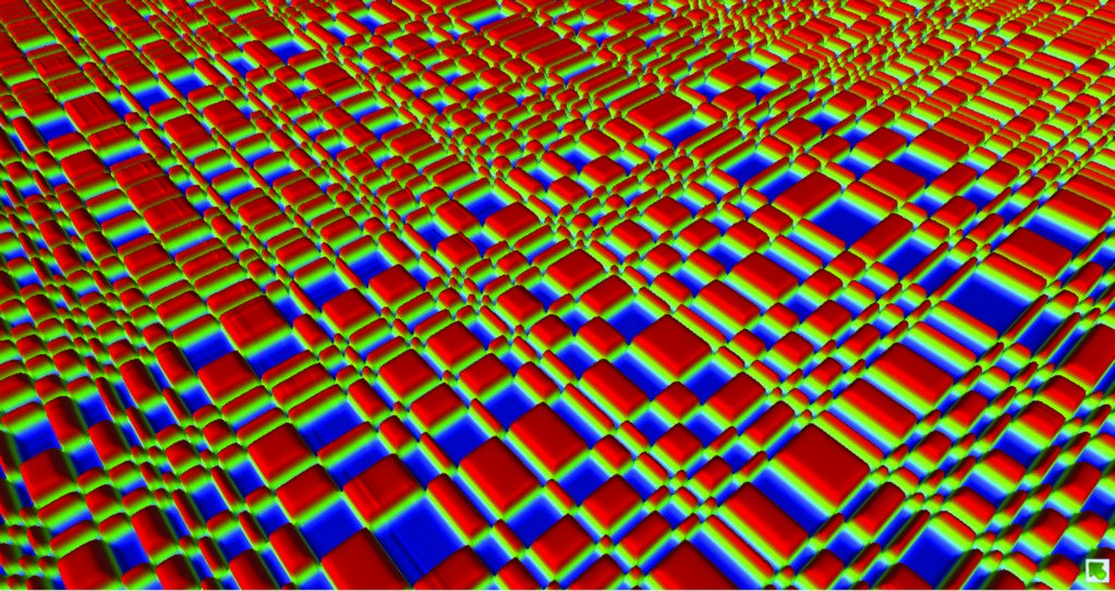
Figure 1: Grating structure with a pseudo random lateral periodicity and ~70nm tall features, as measured using the Bruker Contour GT-X micro-interferometer. This composite map was created by stitching together >100 images and illustrates how optics can be imaged over large areas with sub-micron lateral resolution.
Super-precision at-wavelength metrology
Several at-wavelength metrology methods have been implemented and further improved at Diamond. The method based on speckle scanning technique is the most promising as we have demonstrated that the angular sensitivity for measuring the slope error of an optical surface can reach an accuracy in the range of two nanoradians3. When compared with conventional ex situ metrology techniques, the method enables a substantial increase of around two orders of magnitude in the angular sensitivity and opens the way to a previously inaccessible region of slope error measurement. The method has been employed for characterisation of X-ray mirrors and lenses.
Apart from beam focusing to a micrometer or nanometer beam size, the generation of 'top-hat' beams of variable size is increasingly desired by many X-ray synchrotron users, in particular to reduce the radiation damage on fragile samples. Hence, active optics such as bimorph and mechanically bent mirrors are widely used for beam shaping since they permit a wide choice of focal lengths and beam sizes. Generally, the optimisation of such mirrors is often complicated and time consuming.
Here an example of in situ characterisation and optimisation of a microfocusing bimorph mirror by using the speckle scanning technique is given. As illustrated in Fig. 2, the experimental setup of the speckle based technique is simple and robust. Since the speckle-generating-membrane can be freely located out of the focal plane, the sample position does not need to be accessed. The mirror is optimised by changing the voltages on the 8 piezo electrodes using feedback from the speckle scanning technique. Fig. 3(a) shows the optimised micro-focused beam.
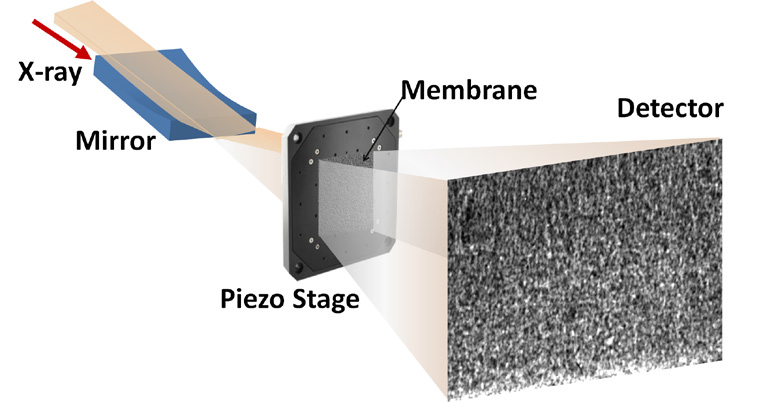
Figure 2: Schematic layout of the in-situ optimisation of a bimorph mirror by advanced metrology based on the speckle scanning technique. The wavefront aberration can be retrieved with high precision by analysing the speckle pattern.
The bimorph mirror can also provide different beam sizes at the sample position by changing its surface to different elliptical forms. To verify the focus and defocus optimisation, a series of images was taken by a high-resolution X-ray camera along the beam direction. Fig. 3 shows the intensity profiles around the focal plane of the bimorph mirror for three cases. A sharp submicron size focus is achieved when the mirror focal plane overlaps with the sample position as in Fig. 3(a). Fig. 3(b) and Fig. 3(c) show the moderate and strong defocus optimisation results and the focal planes moving upstream towards the mirror while the intensity profile remains reasonably uniform at the sample position. As shown in Fig.3, the bimorph mirror was optimised from an initially focused beam size of 0.6μm full width at half maximum (FWHM) to defocused beam up to 25μm FWHM and 50μm FWHM in a controlled way. Even though the beam size is defocused more than 40 times, the fluctuation of structures on the plateau from case (c) is only 11% (standard deviation/mean intensity), thanks to the extremely small slope error polished by the elastic emission technique at JTEC, Osaka. This is quite advantageous for the beamline users compared to a typical X-ray focusing mirror where defocusing by a factor of two or three times the focal size produces unacceptable structures in the beam shape.
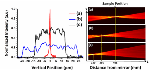
Figure 3: (Left) The measured vertical beam size at the sample position (marked with solid yellow line in right figure) and corresponding intensity profiles as a function of distance from mirror for three cases: (a) Focused beam (b) Moderate defocused beam (c) Strong defocused beam. The yellow dotted lines mark the focal planes.
Here we would like to emphasise that both the focusing beam and the 'tophat' defocused beam by optimising the bimorph mirror in a single iteration. Such a high-precision metrology technique will be extremely beneficial for the manufacture and in situ alignment / optimisation of X-ray optics for nextgeneration synchrotron beamlines.
References:
1. Wang H., Berujon S., Herzen J., Atwood R., Laundy D., Hipp A. and Sawhney K. X-ray phase contrast tomography by tracking near field speckle. Scientific Reports, 5, 8762 (2015).
2. Wang H., Kashyap Y., Sawhney K. Hard-X-Ray Directional dark-field imaging using the speckle scanning technique. Physical Review Letters, 114, 103901 (2015).
3. Wang H., Sutter J., Sawhney K. Advanced in situ metrology for x-ray beam shaping with super precision. Optics Express, 23, 1605-1614 (2015).
4. Alcock SG., Nistea I., Sutter JP., Sawhney K., Ferme´JJ., Thellièr C and Peverini L. Characterization of a next-generation piezo bimorph X-ray mirror for synchrotron beamlines. J. Synchrotron Radiation, 22, 10-15 (2015).
5. Laundy D., Alianelli L., Sutter J., Evans G and Sawhney K. Surface profiling of X-ray mirrors for shaping focused beams. Optics Express, 23, 1576-1584 (2015).
6. Wang H., Sawhney K., Berujon S., Sutter J., Alcock SG., Wagner U. and Rau C. Fast optimization of a bimorph mirror using x-ray grating interferometry. Optics Letters, 39, 2518-2521 (2014).
7. Sutter, J. P., Chubar., O. and Suvorov., A. Perfect crystal propagator for physical optics simulations with Synchrotron Radiation Workshop. Proc.- SPIE 9209, 92090L (2014).
8. Sutter, J. P., Alcock., S. G., Rust, F., Wang, H. and Sawhney, K. Structure in defocused beams of X-ray mirrors: causes and possible solutions. Proc.- SPIE 9208, 92080G (2014).
9. Laundy, D., Alcock, S. G., Alianelli., L., Sutter., J. P., Sawhney, K. J. S. and Chubar. O. Partial coherence and imperfect optics at a synchrotron radiation source modeled by wavefront propagation. Proc.-SPIE 9209, 920903 (2014).
10. Wang H., Berujon S., Sutter J., Alcock SG., Sawhney K. At-wavelength metrology of x-ray optics at Diamond Light Source. Proc. SPIE-9206, 920608 (2014).

Diamond Light Source is the UK's national synchrotron science facility, located at the Harwell Science and Innovation Campus in Oxfordshire.
Diamond Light Source Ltd
Diamond House
Harwell Science & Innovation Campus
Didcot
Oxfordshire
OX11 0DE
Copyright © Diamond Light Source. Diamond Light Source® and the Diamond logo are registered trademarks of Diamond Light Source Ltd
Registered in England and Wales at Diamond House, Harwell Science and Innovation Campus, Didcot, Oxfordshire, OX11 0DE, United Kingdom. Company number: 4375679. VAT number: 287 461 957. Economic Operators Registration and Identification (EORI) number: GB287461957003.