Richard Walker, Technical Director
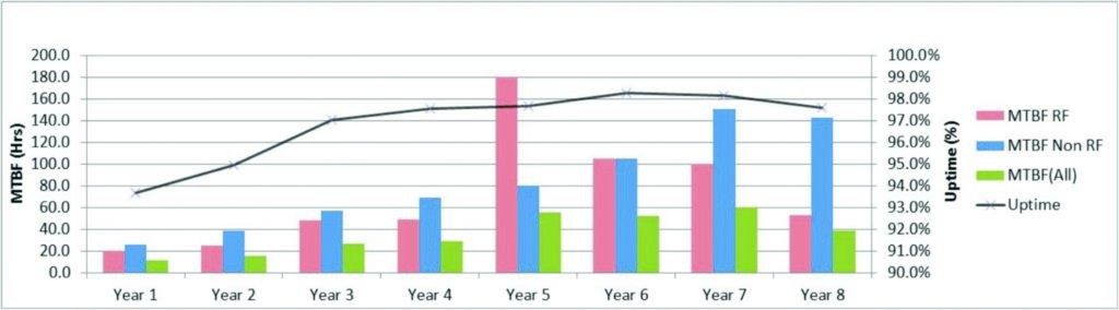
In 2014/15, Diamond’s eighth year of operations, a total of 206 days (4,944 hours) were scheduled for beamline operations; 201 days of User Mode, and five beamline start-up days. These figures are based on the revised schedule issued in September 2014 following the failure of one of the superconducting radiofrequency (RF) cavities earlier that month. The majority of the beam delivery was in standard multibunch mode (900 bunch train) or 'hybrid' mode (686 bunch train + a single bunch) with total current of 300 mA. In addition there were several periods of 'Special Beam Conditions', six days in June 2014 and four days in March 2015 of 'low-alpha' mode, to produce short bunches (3.5 ps rms), as well as two days in August 2014 and four days in December 2014 of 156 bunch mode, with 135 mA total current. Operation with all filling patterns was carried out in top-up mode.
The annual operating statistics are shown in Fig. 1. Unfortunately, the unexpected RF cavity failure has had a major impact on reliability. The cavity had to be removed from the ring and replaced with a new cavity that had not had sufficient time for full conditioning in the RF Test Facility. As a result, we subsequently suffered a much greater number of beam trips due to cavity vacuum events while the cavity conditioned in the ring. The Mean Time Between Failures (MTBF) for the year was 38.6 hours, significantly less than the figures both for the previous year (60.3 hours) and the first five months of the year before the cavity failure (51.6 hours). Fig. 1 shows the MTBF separately for the RF system and all other non-RF trips and it can be seen that the incidence of non-RF trips remained very similar to the previous year, which is encouraging. The overall uptime (beam delivered as a percentage of scheduled hours, excluding low-alpha operation) also decreased slightly to 97.6%, whereas it had been in excess of 98% in the previous two years.
Scheduled shutdowns in 2014/15 continued to be very busy, particularly with installations and modifications related to the beamline development programme. Front-ends were installed for beamlines I14 and I21, and the final in-vacuum undulator was installed for the Coherence branchline (I13- 1), replacing the temporary standard in-vacuum device, with 2 m magnetic length, with a special 2.7 m long device.
Double-Double Bend Achromat (DDBA) Project
The DDBA project, described in last year’s Annual Review, will see a complete DBA (double bend achromat) cell of the storage ring replaced with a new DDBA structure, which will convert what would otherwise be a standard bending magnet beamline into a much more powerful insertion device beamline, with a full length in-vacuum insertion device as its source. The project has progressed considerably in the last year, towards the scheduled installation date of August 2016. Designs have been completed and contracts placed for all of the new magnets and vacuum vessels as well as the two girders on which they will be assembled (Fig. 2).
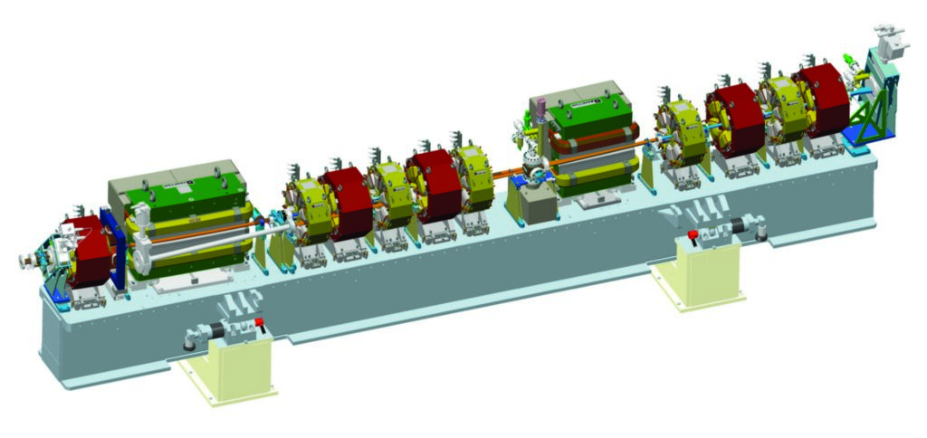
Figure 2: Model of one of the two girder assemblies that make up the new DDBA cell.
In order to accommodate the increased number and higher strength magnets into the ring, all of them will have significantly reduced size compared to the existing ring magnets, as shown in Fig. 3.
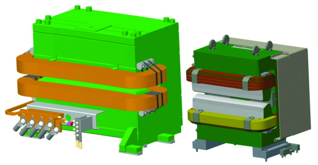
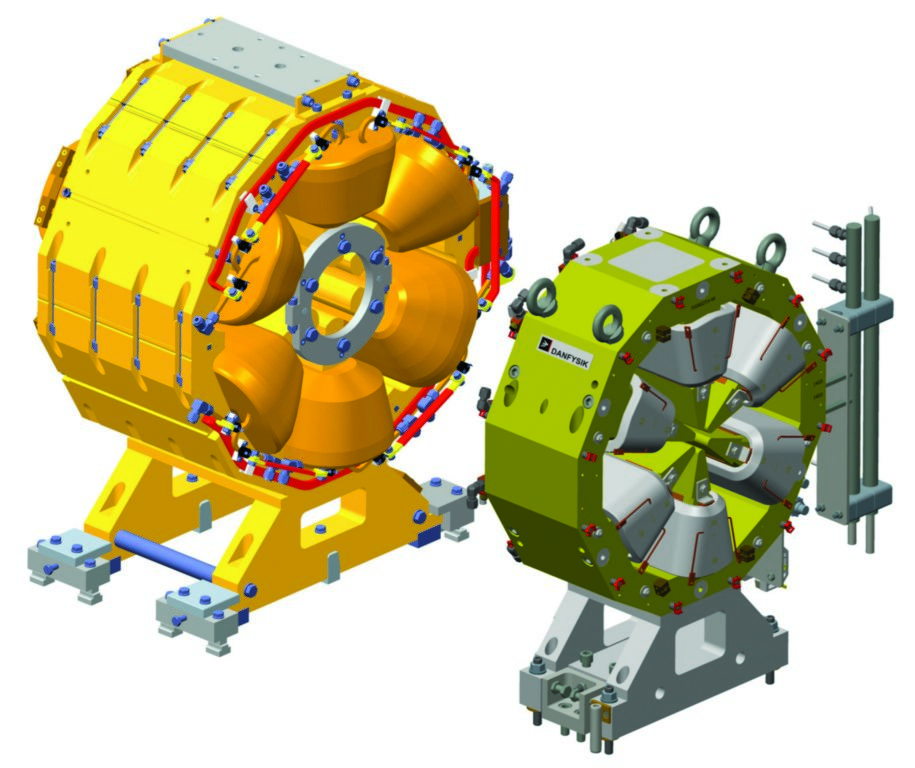
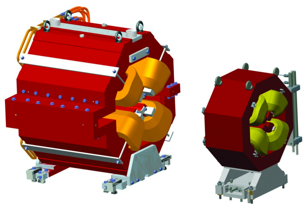
Figure 3: Comparison of the size of the existing ring magnets (left of each pair) with the new DDBA magnets (right of each pair); green - dipoles, red – quadrupoles, yellow – sextupoles.
Limiting the shutdown for DDBA installation to a minimum of eight weeks has meant starting an extensive programme of cabling well in advance. Starting in March 2014, 334 temporary cables have been installed and terminated (Fig. 4). Currently about 50% of systems have been disconnected from the existing cables and transferred onto the temporary cables. During future shutdown periods, once the connection to the temporary cables has been completed, the existing cables that will not be re-used will be removed and new cables for the DDBA cell will be installed and terminated. In this way, when the new girder assemblies are installed in August/September 2016 they can be readily connected up to the pre-installed cables.
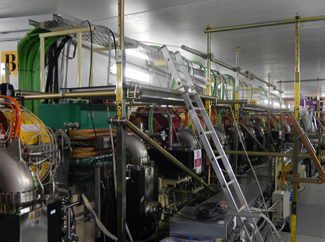
Figure 4: Temporary cable installation in preparation for the DDBA lattice conversion.
Future Developments
In addition to the DDBA project described above, a number of other developments are underway or beginning. In response to the continuing difficulties being experienced with the RF cavities, it has been decided to augment the existing RF system with two normal conducting cavities, of the Higher-Order Mode (HOM) damped cavity design currently in use at the synchrotron facilities ALBA in Spain and BESSY in Germany. The preferred solution which is being worked on is to install the cavities in an adjacent straight section to the existing RF straight, on either side of an in-vacuum insertion device, as shown in Fig. 5. The additional cavities will give greater operating margin which will be especially useful to minimise the impact of any planned, or unplanned, work on the superconducting cavities.
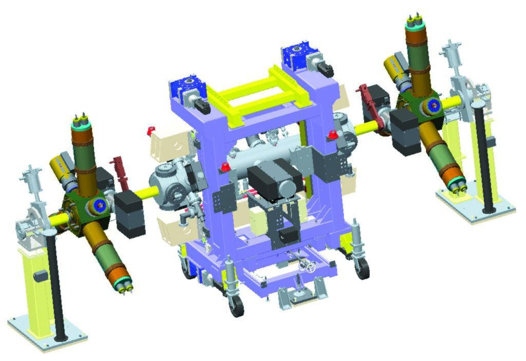
Figure 5: Possible location of two new normal conducting cavities on either side of an invacuum insertion device.
Another development which is underway is that of a new design of a cryogenic permanent magnet undulator (CPMU) which will give a significant increase in brightness compared to the existing in-vacuum undulators. The new CPMU will use PrNdFeB magnetic material which shows significant enhancement of the magnetic properties when cooled to liquid nitrogen temperature. The engineering design which is being carried out in-house includes a number of novel features including the gap change mechanism, the magnetic array support system and the thermo-syphon cooling system (Fig. 6). The first device will be installed on beamline I24, and subsequently several more beamlines will be upgraded with CPMU devices.
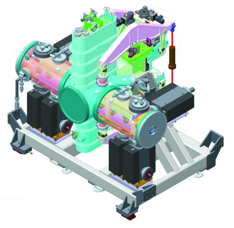
Figure 6: Novel cryogenic permanent magnet undulator (CPMU) being developed at Diamond.
A number of other developments are also being studied. Improvements to orbit stability are being targeted, to reduce the beam motion at high frequency in the vertical plane, and to reduce the disturbance during top-up operation. There is also an aim to improve the longitudinal stability of the bunches by reducing the phase and amplitude fluctuations of the RF power in the cavities. Ways of improving photon stability at the sample are being investigated by means of better diagnostics and new feedback systems. Finally, a design study has commenced for a possible major upgrade of the Diamond machine, Diamond-II, to be complemented by a science case that will take into account the impact of such an upgrade on all beamlines at Diamond.
There is also an aim to improve the longitudinal stability of the bunches by reducing the phase and amplitude fluctuations of the RF power in the cavities. Ways of improving photon stability at the sample are being investigated by means of better diagnostics and new feedback systems. Finally, a design study has commenced for a possible major upgrade of the Diamond machine, Diamond-II, to be complemented by a science case that will take into account the impact of such an upgrade on all beamlines at Diamond.

Diamond Light Source is the UK's national synchrotron science facility, located at the Harwell Science and Innovation Campus in Oxfordshire.
Diamond Light Source Ltd
Diamond House
Harwell Science & Innovation Campus
Didcot
Oxfordshire
OX11 0DE
Copyright © Diamond Light Source. Diamond Light Source® and the Diamond logo are registered trademarks of Diamond Light Source Ltd
Registered in England and Wales at Diamond House, Harwell Science and Innovation Campus, Didcot, Oxfordshire, OX11 0DE, United Kingdom. Company number: 4375679. VAT number: 287 461 957. Economic Operators Registration and Identification (EORI) number: GB287461957003.