
___________________________________
Industrial Liaison Group:
Tel: +44 (0) 1235 778797
E-mail: [email protected]
Three-dimensional micron-scale imaging of electrodeposited lithium ...Read On I13 in the Annual Review
A recent study published inTransport in Porous Media by a team of researchers from Imperial College has enhanced our understanding of the behaviour of carbon dioxide (CO2) when injected into subsurface geology.
Despite the UK’s positive performance in reducing its CO2 emissions1, global emissions from fuel combustion continue to rise2, raising long-term CO2 storage challenges to offset the predicted increase. Currently subsurface geological sites are considered one of the most promising candidates for the long-term sequestration of carbon dioxide3.
A viable geological carbon store would be sufficiently porous (sedimentary rocks containing depleted hydrocarbon reservoirs and aquifers bear this characteristic) and simultaneously trapped by overlying non-permeable strata such as volcanic basalt, or a clay layer.
It is estimated that a total of 2,600 billion metric tons of CO2 could be sequestered this way in the USA alone4. It is also predicted that the market for carbon storage techniques will expand considerably due to rapid extraction of coal by industrialising nations, and sequestration technologies may act as a counterbalance to the predicted elevation in emissions5. This study provides very useful benchmark data for future modeling and site assessment, and suggests the validity of safe long-term geo-sequestration.
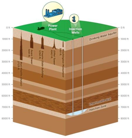 Figure 1: Schematic of carbon capture and storage showing a typical depth of which CO2 would be injected. Courtesy of United States Environmental Protection Agency (http://www3.epa.gov/climatechange/ccs/).
Imaging CO2 injection
In carbon storage, CO2 from the exhaust stream of a power station is injected deep underground into porous rock. The physical and chemical properties that determine the movement and long-term fate of injected CO2 are all controlled by processes at the pore, or micron scale. The Diamond Manchester Imaging Branchline (I13-2) at Diamond Light Source provides a highly intense beam and extremely fast detectors that combine to enable rapid data collection. The research team took advantage of these capabilities to observe fluid flow under typical conditions. This means measuring at the pore scale, at high temperatures and pressures that are encountered in storage aquifers.
According to Dr Branko Bijeljic, Senior Research Fellow at Imperial College's Department of Earth Science and Engineering, and Principal Investigator on the study: "previously it had been a considerable challenge to mimic subsurface conditions. Using I13-2 allowed us to observe dynamics of CO2 flow in a carbonate rock formation at conditions similar to those encountered within the Earth's crust, rendered down to a resolution of several microns and time slices at intervals of tens of seconds.”
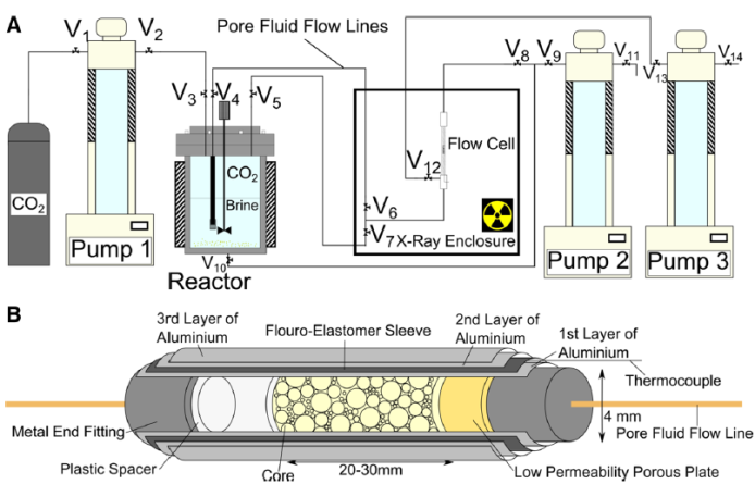
Figure 2: Experimental flow apparatus used in this experiment. A) High-pressure syringe pumps were connected to the flow cell and reactor using flexible flow lines. B) Detail of the core assembly showing aluminium core wraps to prevent the diffusive exchange of CO2 across the flouro-elastomer sleeve, a low-permeability porous plate used for flow control, and the PTFE spacer used to monitor the CO2 –brine interface during system pressurisation. Valves are numbered V1−14. Courtesy of Andrew et al, 2015.
Dr Bijeljic’s team focused on the dynamic processes at play during injection of supercritical CO2, such as multiphase flow and reactive transport at a range of conditions. This has allowed them to observe key events such as drainage (injection into brine-saturated rock, Video 1, Fig. 3) and subsequent displacement by brine as the CO2 migrates underground, which can lead to a safer storage.
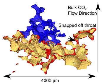 Figure 3: A rendering of a large drainage event. Regions occupied by CO2 after the jump but not before shown in blue, the regions occupied by CO2 both before and after the event shown in yellow and the regions occupied before but not after the event shown in red. This shows not only the interface recession resulting from the quasi-static capillary pressure change associated with the drainage event, but also the snap-off of one of the throats occupied by CO2 prior to the jump. Courtesy of Andrew et al, 2015.
Dr Bijeljic adds, "Wherever the CO2 moves, it can leave behind a trail of blobs trapped in the pore space. We have observed the formation of these so-called ganglia for the first time at reservoir conditions. The work shows that migration and leakage of CO2 is unlikely, since the CO2 will become largely or entirely trapped in the rock."
What this means
By demonstrating how injected CO2 in its own phase is trapped, and how dissolved CO2 reacts with the host rock, Dr Bijeljic confirms that the team has elucidated the processes that determine the long-term fate of CO2 in the subsurface: "Our findings help us achieve the goal of safe CO2 injection and maintenance of storage sites."
He continues: "Flow and reactive transport between CO2 saturated brine and solid rock has provided new insights into how CO2 behaves underground, including the change in pore space due to dissolution of rock surface by brine equilibrated CO2." The channel growth due to rock dissolution is presented in Video 2.
"This allows us to visualise and quantify the arrangement CO2 and brine in selected carbonate and sandstone samples during CO2 and water injection on a pore by pore basis. Moreover, these pore-scale experiments provide very useful benchmark data for validation of pore-scale models for multi-phase flow and reactive transport in porous media."
The work also promises extensive practical applications that could be of great benefit to society, aside from obvious atmospheric benefits gained from securely capturing CO2. According to Dr Bijeljic, the team's efforts have expanded further into multiphase flow in oil recovery processes and diffusive processes in contaminant transport.
For more information on the I13 beamline, or to discuss potential applications, contact the Diamond Industrial Liaison Team on +44 (1)235 778797 or [email protected]
Funding for the study was provided by the Imperial College Consortium on Pore-Scale Modelling, and the Qatar Carbonates and Carbon Storage Group, provided jointly by Qatar Petroleum, Shell, and Qatar Science and Technology Park.
“Without the support of Professor Christoph Rau and Dr Joan Vila-Comamala to adapt the beamline for dynamic multiphase flow and reactive transport systems, we would not have been able to carry out this important work.”
Branko Bijeljic, Imperial College London.
Vidoe 1: Multiphase flow - drainage of supercritical CO2 in brine saturated rock. Red colour represents CO2 drainage in rock sample.
Video 2: Reactive flow - channel growth due to dissolution of rock surface by brine equilibrated CO2. Video shows both 12 minutes and 120 minutes into the experiment.
1. Department of Energy & Climate Change. UK Greenhouse Gas Emissions: 2nd Quarter 2015 Provisional Figures. 2015 p10. Available from https://www.gov.uk/government/uploads/system/uploads/attachment_data/file/466217/Quarterly_statistical_release_Q2_2015.pdf (accessed 9/10/15).
2. International Energy Agency. CO2 Emissions from Fuel Combustion: Highlights (2014 Edition). 2014 p.112. Available from http://www.iea.org/publications/freepublications/publication/CO2EmissionsFromFuelCombustionHighlights2014.pdf (accessed 9/10/15)
3. British Geological Survey. How can CO2 be stored? Available from http://www.bgs.ac.uk/discoveringGeology/climateChange/CCS/howcanCO2bestored.html (Accessed 9/10/15).
4. National Energy Technology Laboratory. NETL’s 2015 Carbon Storage Atlas shows increase in US CO2 storage potential. 28/9/15. Available from http://netl.doe.gov/newsroom/news-releases/news-details?id=f80b856f-8b25-497c-8a14-1680099b4063 (accessed 9/10/15).
5. Research and Markets. CO2 Capture and Storage (CCS) Market (2014-2020). 2015. Available from http://www.businesswire.com/news/home/20150915005965/en/Research-Markets-Global-Co2-Capture-Storage-CCS#.Vfr9sZetRY4 (Accessed 9/10/15).
Andrew M., Menke H., Blunt MJ. and Bijeljic B. The Imaging of Dynamic Multiphase Fluid Flow Using Synchrotron-Based X-ray Microtomography at Reservoir Conditions. Transport in Porous Media 110 (1), pp. 1-24 (2015). DOI 10.1007/s11242-015-0553-2

Diamond Light Source is the UK's national synchrotron science facility, located at the Harwell Science and Innovation Campus in Oxfordshire.
Copyright © 2022 Diamond Light Source
Diamond Light Source Ltd
Diamond House
Harwell Science & Innovation Campus
Didcot
Oxfordshire
OX11 0DE
Diamond Light Source® and the Diamond logo are registered trademarks of Diamond Light Source Ltd
Registered in England and Wales at Diamond House, Harwell Science and Innovation Campus, Didcot, Oxfordshire, OX11 0DE, United Kingdom. Company number: 4375679. VAT number: 287 461 957. Economic Operators Registration and Identification (EORI) number: GB287461957003.

 Industrial Liaison Office