
To date, the development of inert anode materials has relied on the characterisation of samples which have been removed from their operational environment at various pre-defined points of interest1. This ex situ approach can be problematic, as conventional analysis techniques typically require some form of sample preparation, ranging from simply allowing the sample to cool, to more invasive procedures such as cutting and polishing. While any material studied outside of its operational environment will be altered to some extent, friable surface layers, crucial to the understanding of reaction mechanism, are at particular risk. Obtaining clear information about how these layers evolve during cell operation, without disrupting their fragile structure, requires a quantitative in situ characterisation method.
Molten-salt electrolysis is used extensively in the production of light metals such as aluminium, lithium and magnesium, and is being investigated2 as a potential replacement for the Kroll3 process for titanium production. Currently, reactive carbon anodes are used in titanium electrowinning research with many unwanted outcomes, such as the emission of greenhouse gases, reaction of carbon with the electrolyte, and carbon contamination of electrowon metal. Conversely, an ideal inert anode is not consumed during the electrolysis, does not react with the electrolyte and produces only oxygen, therefore having a much lower impact on process control and the environment. However, inert anodes are prone to failure as, in practice, they are attacked by both the electrolyte and the oxygen evolved at the anode. In order to develop these new anode materials further, a detailed understanding of the structural and chemical changes that lead to their failure is needed.
Due to the aggressive sample environment, molten calcium chloride at 950 °C, the in situ characterisation of inert anodes employed in molten-salt electrochemistry is difficult. A 'see-through cell', developed by McGregor et al4., which uses a transparent quartz crucible for the direct observation of both the anode and cathode, has given many insights into physical aspects of anode behaviour; however, determining chemical and structural changes in an operational anode requires a different approach. In order to study structural changes in materials with respect to time, synchrotron and neutron diffraction techniques are often used. The intensity of such advanced radiation sources allows data to be collected on the time scales necessary to observe reaction changes and investigate their kinetics.
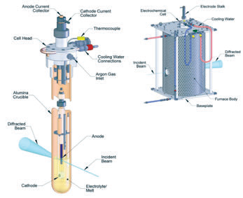 |
| Figure 1: Schematics of the (a) electrowinning cell and (b) furnace. |
This experiment, performed at beamline I12, aimed to look at the formation of surface layers on the anodes whilst they were operating in molten salt at 950°C, required; (i) highly penetrating radiation in order to pass through the furnace walls and several centimetres of electrolyte, (ii) high spatial resolution in order to selectively study only the anode surface in a complex sample environment and (iii) high temporal resolution in order to study the changes in the anode on a minute by minute basis. Synchrotron-based energy-dispersive X-ray diffraction (EDXRD) is uniquely suited to fulfil these experimental requirements as its characteristics include; (i) penetrating high-energy X-rays, (ii) a fixed detector position, allowing tight collimation of the diffracted beam, providing good spatial resolution, and (iii) a very high intensity beam allowing for short data acquisition times. In order to carry out this work, an electrowinning cell and furnace, Fig. 1 was designed5 to allow for the safe operation of a molten-salt electrochemical cell in a beamline environment whilst still allowing for valid diffraction data to be obtained. The guiding principle behind the design of the cell and furnace was to enable in situ characterisation of an inert anode using EDXRD, without compromising the electrochemical reactions at either the anode or cathode.
| |
| Figure 2: Accumulated EDXRD D patterns as a function of time for data collected top and bottom the electrolyte. The transformation of the Magnéli (M) phases into rutile (R) can be seen clearly. (Fluorescence peaks, which are constant throughout the experiment and incidental to the reaction, are designated 'f'.) Differences in the relative intensities between the two datasets is due to the absorption of low energy X-rays in the electrolyte. |
The electrowinning cell was designed to minimise the X-ray beam path through the electrolyte, while still allowing sufficient electrolyte for electrolysis to occur. The furnace was designed to reach a maximum of 1100°C, while only using a standard 240 V, 10 A power supply.
The anodes used in this study were a Magnéli-phase material (EbonexTM; containing TinO2n-1, n = 4–6)6. This material oxidises to rutile (TiO2) due to the evolution of oxygen at the anode surface, producing a passivation layer which ultimately causes the anode to fail. EbonexTM was used as a model anode as; (i) the phase changes that occur in this material during electrolysis have been substantially characterised ex situ1 allowing findings made during in situ experimentation to be corroborated by ex situ data, (ii) it does not contaminate the electrolyte or cathode, and (iii) it remains dimensionally stable.
In separate experiments, in situ EDXRD data were collected above or below the surface of the electrolyte to observe the effect of electrolyte absorption on the diffracted intensities; electrolysis is still possible slightly above the surface of the electrolyte as it creeps up the surface of the anode. Datasets were collected for 60 sec, with a 5 sec delay between consecutive datasets, for the duration of the experiment, typically 6-7 hours. Accumulated diffraction patterns collected centrally on the anode are shown in Fig. 2; top and bottom the surface of the electrolyte. The oxidation of the Magnéli-phases to rutile can be seen clearly. For the data collected above the electrolyte, the diffraction peaks for each phase are clearly visible. For the data collected below, the diffraction peaks for each phase are less visible due to the absorption of lower energy X-rays by the electrolyte.
| |
| Figure 3: Results of quantitative phase analysis of the EDXRD data collected (a) above and (b) below the surface of the electrolyte. |
The data were analysed quantitatively using the Rietveld7 method to track the evolution of the various phases present in the anode. Scarlett et al8 had previously developed this methodology for the quantitative analysis of EDXRD data which uses the energy spectrum of the incident beam, sample absorption, and the crystal structures of the anode materials in order to calculate a model diffraction pattern. Such a model was then refined against the EDXRD data in order to extract quantitative phase analyses. Fig. 3 shows the results of this quantitative phase analysis. It can be seen that in all systems, rutile forms at the expense of both Magnéli phases equally.
The similarities in the quantitative phase analysis both above and below the electrolyte surface suggest that it is possible to obtain meaningful in situ diffraction data with the incident beam just above the electrolyte, mitigating the deleterious effect of X-ray absorption on the resultant diffraction patterns. Initial kinetics modelling suggests that the limiting factor in the growth of the rutile layer is the rate of solid-state diffusion of oxygen within the anode structure. This continual monitoring of the rutile phase fraction throughout the duration of the experiment revealed the way in which the layer grows, something that would be very difficult to do accurately via ex situ experimentation. It also confirms the absence of any intermediate phases which would not be observed using traditional post mortem methodologies.
Rowles, M. R., Styles, M. J., Madsen, I. C., Scarlett, N. V. Y., McGregor, K., Riley, D. P., Snook, G. A., Urban, A. J., Connolley, T. & Reinhard, C. Quantification of Passivation Layer Growth in Inert Anodes for Molten Salt Electrochemistry by In Situ Energy-Dispersive Diffraction. J. Appl. Cryst. 45(1), 28-37 (2012)
We acknowledge travel funding provided by the International Synchrotron Access Program (ISAP). ISAP is an initiative of the Australian Government being conducted as part of the National Collaborative Research Infrastructure Strategy. M. J. Styles gratefully acknowledges receipt of a full PhD scholarship from the CSIRO Flagship Collaboration Fund, and additional funding from the CSIRO Light Metals Flagship.

Diamond Light Source is the UK's national synchrotron science facility, located at the Harwell Science and Innovation Campus in Oxfordshire.
Copyright © 2022 Diamond Light Source
Diamond Light Source Ltd
Diamond House
Harwell Science & Innovation Campus
Didcot
Oxfordshire
OX11 0DE
Diamond Light Source® and the Diamond logo are registered trademarks of Diamond Light Source Ltd
Registered in England and Wales at Diamond House, Harwell Science and Innovation Campus, Didcot, Oxfordshire, OX11 0DE, United Kingdom. Company number: 4375679. VAT number: 287 461 957. Economic Operators Registration and Identification (EORI) number: GB287461957003.

 Science