

 Diamond Annual Review 2016
 | ||
Monitoring the bonding of CO molecules on a single Pd nanoparticle |
Related publication:
Yim CM, Pang CL, Hermoso DR, Dover CM, Muryn CA, Maccherozzi F, Dhesi SS, Pérez R, Thornton G. Influence of support morphology on the bonding of molecules to nanoparticles. Proceedings of the National Academy of Sciences of the United States of America 112, 7903-7908, doi:10.1073/pnas.1506939112 (2015).
Keywords:
μ-NEXAFS; STM; Nanoparticle; Carpet growth; Surface strain; Adsorption.
Metal nanoparticles form the basis of heterogeneous catalysts because they offer a bigger surface area compared to bulk metal, which increases catalytic activity. To optimise performance, it is important to know how molecules adsorb to them compared to single crystals. Palladium (Pd) nanoparticles supported on a substrate of titanium dioxide, TiO2(110), were selected as the test system because it is familiar and well understood.
Experiments were performed on the Nanoscience beamline (I06). The Spectroscopic Photoemission and Low-Energy Electron Microscope at I06 provides real-time imaging at a high spatial resolution of 22 nm in the energy-filtered photoemission electron microscopy (XPEEM) mode. This is ideal for single nanoparticle micro-focus Near Edge X-ray Absorption Fine Structure (μ-NEXAFS) allowing non-destructive chemical analysis.
μ-NEXAFS data shows that carbon monoxide (CO) adsorbs with its molecular axis approximately perpendicular to the nanoparticle top facet. In complementary scanning tunnelling microscopy (STM) measurements, the CO registry on the nanoparticle is found to be different from the single crystal. Theoretical calculations suggest that the difference is caused by strain on the nanoparticle induced by carpet growth across the substrate step edges. This opens up the possibility of tailoring nanoparticle functionality by tuning the morphology of the substrate. These results also provide a crucial insight into the workings of a heterogeneous catalyst, for instance in automobile exhaust catalysis where CO is oxidised to carbon dioxide (CO2).
Surfaces and Interfaces Village | Beamline I06
Supported metal nanoparticles often exhibit properties differing from those of their single crystal counterparts. There have been several explanations for this, including quantum size effects, strong metal support interactions, and some interplay between facets. However, it is not fully understood how other factors such as the support morphology affect the adsorption behaviour of nanoparticles. To elucidate this, we chose the system of CO/ Pd{111} nanoparticles supported on TiO2(110) as our model. Two techniques were employed, namely μ-NEXAFS and STM to characterise the bonding of CO molecules on the Pd{111} nanoparticles.
Previous studies of CO/Pd{111} nanoparticles assumed CO to bond more or less upright on the surface, as it is on native Pd(111)1. To test this assumption, μ-NEXAFS measurements isolated to a single Pd{111}-oriented nanoparticle, Surfaces and Interfaces Village Beamline I06 were performed; to the authors' knowledge, this is the first occasion that such a measurement has been reported. Taking μ-NEXAFS data in this way eliminates averaging over an ensemble of nanoparticles. Carbon K-edge μ-NEXAFS were taken from a 1.5 μm wide Pd nanoparticle covered with 0.5 ML of CO (inset of Fig. 1b) at a fixed incidence angle of 16˚ with different polarisation angles (β), where β = 90˚ (0˚) corresponds to s- (p-) polarised light, the electric field vector of which lies perpendicular (parallel) to the plane of incidence. As shown in Fig. 1a, the CO π* intensity signal (I), centered at hν = 287 eV, decreases with decreasing β. By fitting the I versus β data (Fig. 1b) using equations adapted from Stöhr & Outka2, it was determined that the CO axis lies within 21˚± 7˚ of the surface normal. Previous NEXAFS measurements of CO on the native Pd(111) surface reveal an upright bonding orientation1. The authors attribute the discrepancy in the CO bond angle measured from the single crystal in Knight et al.2 and the nanoparticle data here to the signal contribution from CO on the side facets that are not considered in the analysis. Here, the μ-NEXAFS data indicate that there is some similarity in CO bonding to the nanoparticle and single crystal.
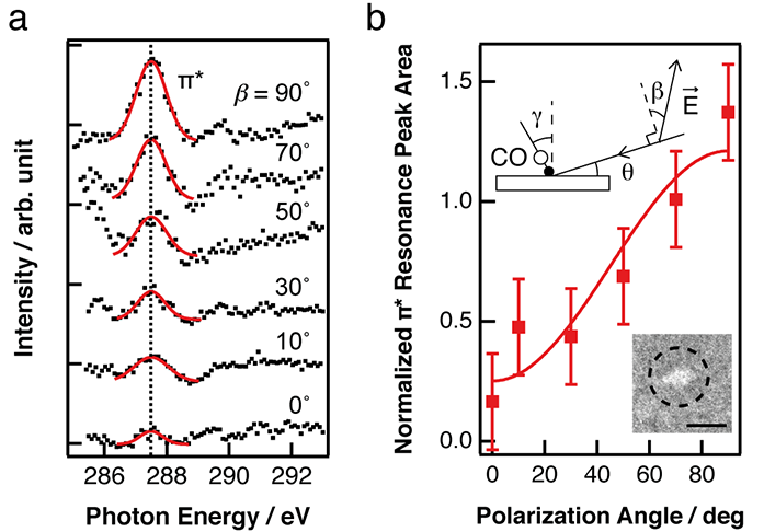
Figure 1: a) Normalised Carbon K-edge μ-NEXAFS spectra recorded at different polarisation angles (β) from a Pd nanoparticle (b, Inset) covered with 0.5 ML CO; b) Integrated intensity of the CO π* resonance peak (I) as a function of β. Markers are the experimental data and the solid line is the numerical fit to the data. (Inset) XPEEM image of the Pd nanoparticle supported on TiO2(110), recorded at hν = 430 eV (scale bar = 2 μm). The particle has a measured diameter of 1.5 μm.
STM was also used to monitor the CO structures forming on the (111) top facet of the Pd nanoparticles. Here, the nanoparticles formed on the TiO2(110) surface typically have an average diameter of 20 nm and height of 2.3 nm. Exposing the Pd/TiO2 surface to CO results in the formation of a number of different overlayers at a CO coverage of 0.5 ML. These include the fcc- and hcp- hollow (HH-) c(4×2)-2CO3 and bridge-bridge (BB-) c(4×2)-2CO (Fig. 2a). These two phases were also formed on the native Pd(111) surface4. Two other c(4×2)-2CO phases that are formed uniquely on the Pd nanoparticles were also observed. They are the atop-bridge (TB-) (Fig. 2a) and atop-hollow (TH-) c(4×2)-2CO (Fig. 2b). A closer inspection at the corresponding macroscopic STM images reveals that the newly observed phases are only formed on the nanoparticles with a curved (111) top facet, arising when they are 'carpet grown' across the substrate step edges. One such nanoparticle is illustrated in Fig. 2d. To form a carpet, the Pd lattice elongates (tensile strain) in the direction across the step edges, and in order to reduce the elastic energy cost, the lattice shrinks (compressed strain) in the orthogonal direction. The authors propose this strain modifies the CO-Pd(111) adsorption behaviour.
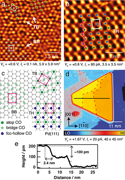
Figure 2: a-b) STM images taken from the curved (111) top facet of the Pd nanoparticles covered with 0.5 ML CO, leading to c(4×2)-2CO structures with atop-bridge (TB) and bridgebridge site occupations in (a), and atop-hollow (TH) site occupations in (b); c) Models of the TB-, BB- and TH- c(4×2)-2CO on Pd(111); d) STM image recorded from a Pd nanoparticle spanning across two step edges of the TiO2 substrate. Red dashed lines mark the locations of the step edges lying beneath the nanoparticle; e) Line plot taken from the black line in (d) showing that the top facet is curved.
To test this idea, DFT with the optB86b vdW functional was employed to study the effect of anisotropic strain on the stability of different c(4×2)-2CO structures on Pd(111). In the calculations, tensile strain (εs > 0) is modeled by elongation along the [1-01] together with compression along the [1-21-] (see Fig. 3b), and vice versa for compressive strain (εs < 0). As shown in Fig. 3a, with no surface stress, the HH overlayer has the lowest energy, followed by BB. As for the TB overlayer, this is unstable in the computation and relaxes to HH. Under both tensile and compressed strains, the gap in the formation energies of the different overlayers becomes smaller. Such a reduction in the energy gap between different phases arises from a reduction in the intermolecular repulsion between CO as the lattice expands along one direction and compresses along another. Note that at εs = +0.04, the TB overlayer relaxes to the more stable TH configuration.
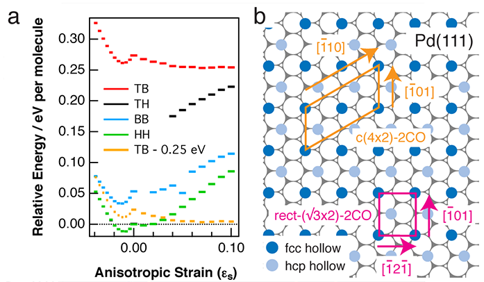
Figure 3: a) Calculated adsorption energies of different c(4×2)-2CO structures and their dependence on anisotropic surface strain: at εs > 0 , the lattice is elongated along [1 - 01] and compressed along [1 - 21 - ], and vice versa at εs < 0. In the calculations, CO molecules are allowed to relax. Orange lines correspond to the TB configuration lowered by 0.25 eV for all εs; b) Ball model showing the c(4×2)-2CO unit cell (in the HH configuration) and equivalent primitive rect-(√3×2) unit cell in relation to Pd(111) azimuths.
The tensile surface strain can lower the energy gap between the TB and HH structures. However, our calculations still predict that the HH overlayer is most stable. This probably arises from the fact that DFT underestimates the cost of breaking one of the bonds from a triply-bonded CO molecule. Given that CO in an atop site is close to being doubly-bonded and that in a hollow site is close to being singly-bonded, it follows that DFT overestimates the strength of CO adsorption in threefold hollow sites. To evaluate how much the vdW functional overestimates the adsorption energy of CO at the hollow site, the difference in the adsorption energies of CO at the atop and fcc hollow sites was calculated using two other functionals; PBE and PBEsol, with the results compared to those obtained by many-body perturbation theory (MBPT)5. In doing so, the authors deduced that the vdW functional employed here overestimates the adsorption energy of CO at the hollow site by 0.25 eV. To take this into account, an extra curve (orange) has been added to Fig. 3a, which is identical to the original TB curve (solid red), but has its formation energies in all surface strain conditions lowered by 0.25 eV. This new curve shows that under tensile strain, TB can be competitive with HH and even have lower formation energy (above εs = +0.04).
Unlike the strain arising from the particle size effect or that from lattice mismatch, which is periodic and incremental in nature, the strain that is caused by particle growth across the substrate step edges is highly localised and abrupt. It may therefore have a more profound effect on gas adsorption in the vicinity of the underlying substrate steps or other lateral discontinuities.
References:
- Knight, M. J. et al. A structural study of a C3H3 species coadsorbed with CO on Pd(111). Surface Science 602, 2743-2751, doi:10.1016/j.susc.2008.06.038 (2008).
- Stöhr, J. & Outka, D. A. Determination of molecular orientations on surfaces from the angular-dependence of Near-Edge X-ray Absorption Fine Structure spectra. Physical Review B 36, 7891-7905, doi:10.1103/PhysRevB.36.7891 (1987).
- Yim, C. M. et al. CO and O overlayers on Pd nanocrystals supported on TiO2(110). Faraday Discussions 162, 191-200, doi:10.1039/c2fd20137b (2013).
- Rose, M. K. et al.Ordered structures of CO on Pd(111) studied by STM. Surface Science 512, 48-60, doi:10.1016/s0039-6028(02)01560-1 (2002).
- Schimka, L. et al. Accurate surface and adsorption energies from many-body perturbation theory. Nature Materials 9, 741-744, doi:10.1038/nmat2806 (2010).
Funding acknowledgements:
This work was supported by EPSRC (UK) EP/G067384, European Cooperation in Science and Technology Action CM1104, The Royal Society and European Research Council Advanced Grant ENERGYSURF (G.T.). D.R.H. and R.P. acknowledge the support of the Project MAT2011-023627 (Ministry of Economy and Competitiveness, Spain) and the computer time provided by the Spanish Supercomputing Network at the Barcelona Supercomputing Center (BSC).
Corresponding author:
Geoff Thornton, University College London, [email protected].
