Instruments by Science Group
I11 Contact
Beamline Phone Number:
+44 (0)1235 778905
Principal Beamline Scientist:
Stephen Thompson
Tel: +44 (0)1235 778546
E-mail:
[email protected]
Science Group Leader
Philip Chater
Email: [email protected]
Tel: +44 (0)1235 778677
I11 High Resolution Powder Diffraction
Status: Operational
Wavelength: 0.5-2.1 Å
Energy: 6-25 (30*) keV - optimised at 15 keV
Energy: 6-25 (30*) keV - optimised at 15 keV
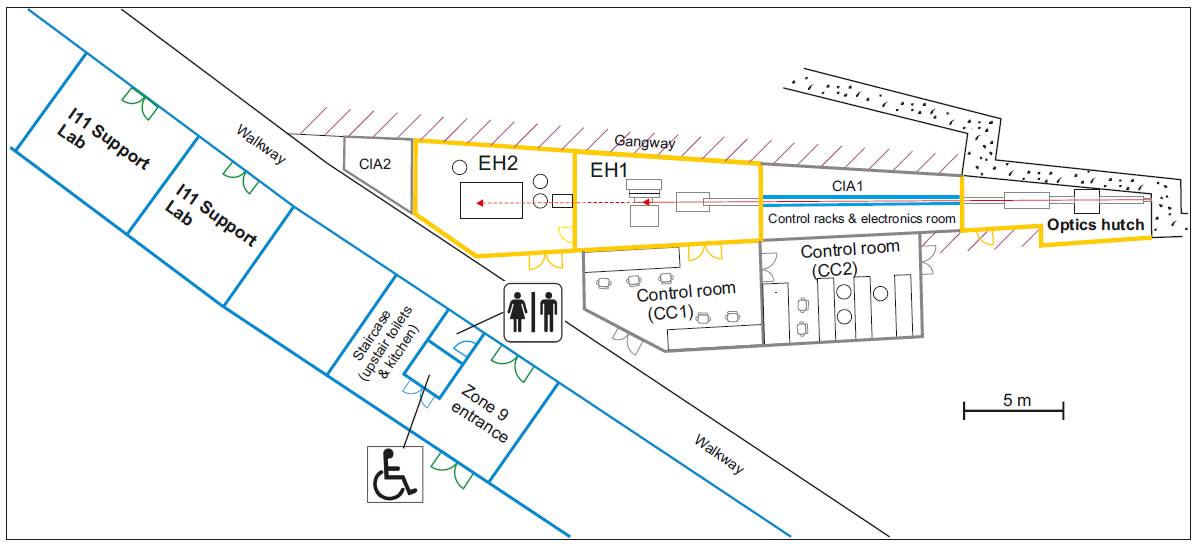
The beamline has three hutches: (i) optics, (ii) experimental hutch 1 and (iii) experimental hutch 2.
The optics hutch houses several slits systems, beam diagnostics, monochromator and harmonic rejection mirrors. The primary slits define the white beam produced by the undulator source. Since greater beam stability is achieved by placing a cryogenic monochromator before the mirror for low vertically divergent beams, a double crystal monochromator is the first optical element, located 27.4 m from the source, and gives a fixed exit-height beam geometry requiring no movement of the downstream components each time energy is changed. The mirror assembly provides harmonic rejection of problematic high energy photons that can pass through the monochromator when working at low energies. To cover the required energy range, a double bounce mirror assembly with three stripe surfaces of Si, Rh and Pt element is used.
Experimental hutch 1 (EH1) is approximately 4.0 m high, 9.7 m long, and 5.0 m wide, narrowing to 3.9 m, and houses a large heavy duty 3-circle diffractometer (θ-, 2θ- and δ-circle). Powder specimens in capillary, flat-plate holder or small sample cells can be attached onto a small xyz-table which is mounted on the inner θ-circle. Larger sample cells and stages can be mounted on a large moveable sample table. High sample throughput (200+ capillary samples) is available via the robotic arm.
For high resolution measurements, the large 2θ-circle provides scanning of positive angles (above the beam) via the use of 5 multi-analysing crystal (MAC) devices, located around the 2θ-circle with a total of 45 individual Si crystals and photomultiplier based detectors with fast pulse shaping electronics.
For time-resolved measurements a wide-angle position sensitive detector (PSD) based on Mythen-2 Si strip modules mounted on the δ-circle is available. The PSD has been specified to perform fast data collection (e.g. 1 powder pattern/s) with a 90º aperture and angular resolution ~ 0.05º for a 0.7 mm diameter capillary sample. To overcome gaps between modules currently two individual scans offset by 0.25º are summed to produce a single continuous diffraction pattern
Experimental hutch 2 (EH2) is approximately 4.0 m high, 7.5 m long and 5.5 m wide and has been specifically designed for Long Duration Experiments (LDE), where samples require weeks to months of periodically monitoring either ‘slow’ changes or long-term rapid cycling. Data is collected using a pixel area detector in transmission geometry. Although most experiemnts will requires the design and production of bespoke sample environments, there are an increasing range of sample environments already available from previous experiments. The beam size at the sample sample is typically 200x200 um.
Space in EH2 is also reserved on one of the motorised stages for normal mode rapid access experiments that may benefit from the use of the area detector

Diamond Light Source is the UK's national synchrotron science facility, located at the Harwell Science and Innovation Campus in Oxfordshire.
Diamond Light Source Ltd
Diamond House
Harwell Science & Innovation Campus
Didcot
Oxfordshire
OX11 0DE
Copyright © Diamond Light Source. Diamond Light Source® and the Diamond logo are registered trademarks of Diamond Light Source Ltd
Registered in England and Wales at Diamond House, Harwell Science and Innovation Campus, Didcot, Oxfordshire, OX11 0DE, United Kingdom. Company number: 4375679. VAT number: 287 461 957. Economic Operators Registration and Identification (EORI) number: GB287461957003.